Spectral imaging of deep tissue

a deep tissue and spectral imaging technology, applied in the direction of optical radiation measurement, spectral modifiers, height/levelling measurement, etc., can solve the problem of weak signals produced in such experiments

Active Publication Date: 2005-03-24
CAMBRIDGE RES & INSTR
View PDF31 Cites 93 Cited by
  • Summary
  • Abstract
  • Description
  • Claims
  • Application Information

AI Technical Summary

Problems solved by technology

The signals produced in such e

Method used


Image

  • Spectral imaging of deep tissue
  • Spectral imaging of deep tissue
  • Spectral imaging of deep tissue

Examples


Embodiment Construction

The invention features a method and apparatus for reducing the detection level of a target compound in deep tissue through spectral discrimination. An important aspect is that a beneficial result is obtained despite the low light levels involved.

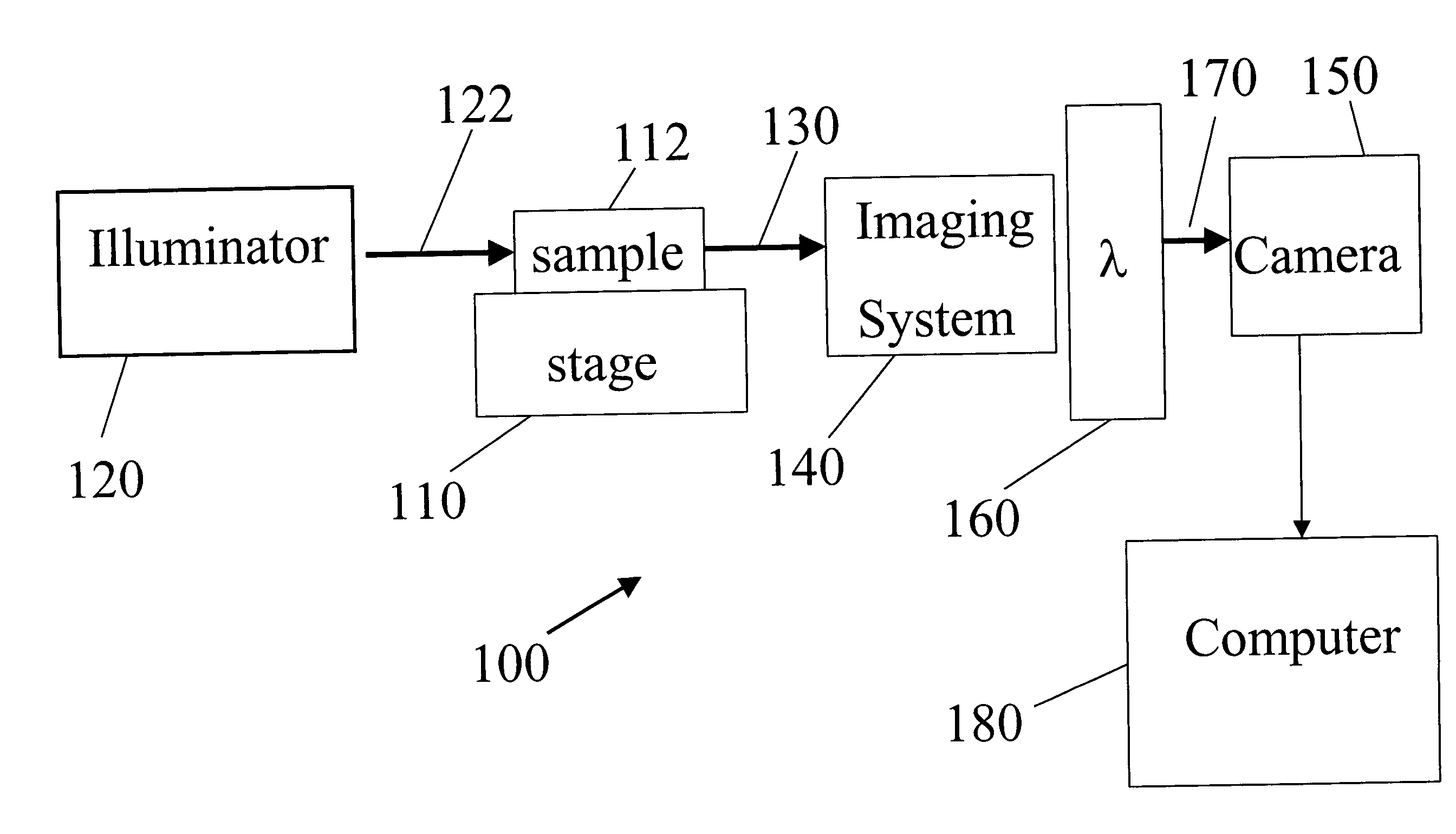
A schematic diagram of a spectral imaging system 100 for imaging deep tissue is shown in FIG. 10. System 100 includes a sample holder 110 suitable for holding a specimen 112 having deep tissue. For example, the specimen may be a living organism, such as an animal or mammel. A target compound is bound to selected portions of deep tissue in the specimen. An illuminator 120 (e.g., a metal halide lamp or other lamp, a laser, an light emitting diode array, or any other source of electromagnetic radiation) directs excitation light 122 to the specimen to excite emission (e.g., fluorescence) from the target compound in the deep tissue. Typically, the excitation light will also cause the autofluoresence from the other components in the specimen. T...


PUM


Abstract

Apparatus and methods are provided for the imaging of structures in deep tissue within biological specimens, using spectral imaging to provide highly sensitive detection. By acquiring data that provides a plurality of images of the sample with different spectral weightings, and subsequent spectral analysis, light emission from a target compound is separated from autofluorescence in the sample. With the autofluorescence reduced or eliminated, an improved measurement of the target compound is obtained.

Description

BACKGROUND Optical imaging of deep tissue is used to probe structures within biological specimens for laboratory research and biomedical purposes. This includes the imaging of internal organs and subdermal tissue in animals such as mice, zebrafish, or humans, and one of the goals is to learn about internal structures without surgery or other intrusive measures. In one technique of deep tissue imaging, fluorescent probes which bind to a specific target in the specimen are imaged by exciting them with illumination light, causing them to fluoresce; the fluorescent emission is separated from the illumination light, which has a different wavelength, by barrier filters and then is detected using a very sensitive camera such as a cooled CCD detector. In other techniques, the specimen is infected with agents that cause it to produce material that is inherently fluorescent, with the most common example being green fluorescent protein (GFP). Further techniques involve use of quantum dots as...

Claims


Application Information

Patent Timeline
IPC IPC(8): A61B5/00G01J3/32G01J3/44G01J3/453
CPCA61B5/0059B82Y5/00B82Y10/00G01J3/32G01J3/4406G01N2201/125G01N21/6486G01N21/255G01N33/4833G01N2201/062G01J3/453
Inventor LEVENSON, RICHARD
Owner CAMBRIDGE RES & INSTR
Why Eureka
Try Eureka