Continuous production membrane water treatment plant and method for operating same

a technology of continuous production and water treatment plant, which is applied in the direction of water treatment parameter control, membranes, reverse osmosis, etc., can solve the problems of inhibiting efficient permeate production, high “fouling” potential of membranes, and exceeding solubility limits, so as to reduce the impact and accelerate the

Inactive Publication Date: 2005-03-31
HW PROCESS TECH
View PDF99 Cites 56 Cited by
  • Summary
  • Abstract
  • Description
  • Claims
  • Application Information

AI Technical Summary

Benefits of technology

[0025] Any of the plant configurations may be implemented using a process-logic-control (PLC) system. The PLC receives measurements from a mix of sensors, such as pressure and temperature sensors and flow meters, to detect a fouling condition in one or more membrane unit(s) and, in response thereto, control the valves necessary to isolate the affected stage or stage increment, redirect the feed stream as needed, and conduct the flushing and washing cycle on the affected stage or stage increment. The PLC system can remove all increments of the various plant stages to be serially, but not necessarily sequentially, removed from service, washed as required, and returned to service. In this manner a full plant wash can be affected without the need for a full plant shut-down or a redundant collection of membrane units. Optionally, the producing, on-line stage or stage increments of the aforesaid described plant can be I / O device monitored, automated valve and variable-frequency-drive (VFD) pump equipped and PLC controlled to produce more or less or the same amount of permeate water as before the stage or stage increment wash process to thereby variously compensate for the permeate loss that accrues to the stage or stage increment removal from service. This can limit the plant loss of permeate to the permeate water production from the removal from service of a stage or stage increment. The pump may be PLC-controlled to relieve the plant of permeate water production volume by feed water turn-down to a point less than that exhibited precedent to the stage or stage increment removal from service. This can lessen the impact of the sometimes large volumes of by-pass water produced accruing to the stage or stage increment removal from service process on the downstream stages or parallel stage increments of the system. The latter case of feed water turn-down is usually effected in response to the removal of a stage from service, not a stage increment, where the diversion of the full feed volume to the stage cannot be accommodated by the following stage and the option of automatic valve “dumping” of water between the stages is precluded for whatever reason.
[0026] In all embodiments of the present invention there is a stage or stage increment isolation process and “flushing” and / or “washing” of the membranes in the isolated vessels. The isolated vessels can be washed in a specific manner, for example, front-end vessel isolation and washing for the lifting of suspended solids can be employed when it is known that there is no potential for solubility-related precipitate occlusion, or a low pH acid dissolution wash might be employed on a tail-end vessel where there is a known violation of the solubility limits for a compound and precipitate occlusion is a predicted, wash maintenance planned, event. These forms of selected washing are quicker to effect and less consumptive of reagent than the “three-stage, high-low-neutral pH, whole plant wash” typically employed by the industry. The stage or stage increments of a plant can be automatic valve plumbed to the wash tanks, reagent feeders and wash pump that attend all membrane water treatment plants. Differing reagent-targeted washes can be used based on the location of a stage or stage increment in the system relative to the type of fouling expected for that part of the system. After the targeted wash and resumption of service, the effect of the wash can be compared to its “standard” performance level to determine the need for a re-wash with either the same or a different reagent. Isolation of stage and stage increments and targeted washing the membranes in a plant can expose membrane units to fewer reagents for shorter periods of time with an implied life-of-membrane benefit.

Problems solved by technology

Membranes can have a high “fouling” potential when used to treat waters carrying organics and dissolved solids (such as salts, hydroxides, polymers, guar, and colloids).
These contaminants can, upon concentration, exceed solubility limits and precipitate and / or form emulsions that occlude the membrane surface and inhibit efficient permeate production.
As permeate water is extracted from a feed water, the concentrate water that lies atop a membrane becomes increasingly contaminated with the dissolved contaminants that are membrane rejected.
Periodically, membranes require washing to remove emulsions and solids partially or fully occluding the membrane surface and impairing membrane performance.
Whole plant washing is a time consuming and reagent consumptive process where all membranes are commonly exposed to all wash reagent types regardless of the degree or type of fouling that may or may not exist on any given membrane surface in the system.
This multiple reagent wash process can reduce the life of the membranes, where the life of membrane is defined by a loss of per-cent rejection efficiency of contaminants from the membrane surface.
Although this configuration can maintain permeate production unchanged during the washing of the third stage filtration array 512, the cost of installing a redundant array is substantial.
Moreover, the redundant array typically only maintains production while one array is washed.
The remaining arrays require an additional respective redundant array, further increasing costs.

Method used


Image

  • Continuous production membrane water treatment plant and method for operating same
  • Continuous production membrane water treatment plant and method for operating same
  • Continuous production membrane water treatment plant and method for operating same

Examples


Embodiment Construction

The Architecture for Monitoring and Controlling Membrane Fouling

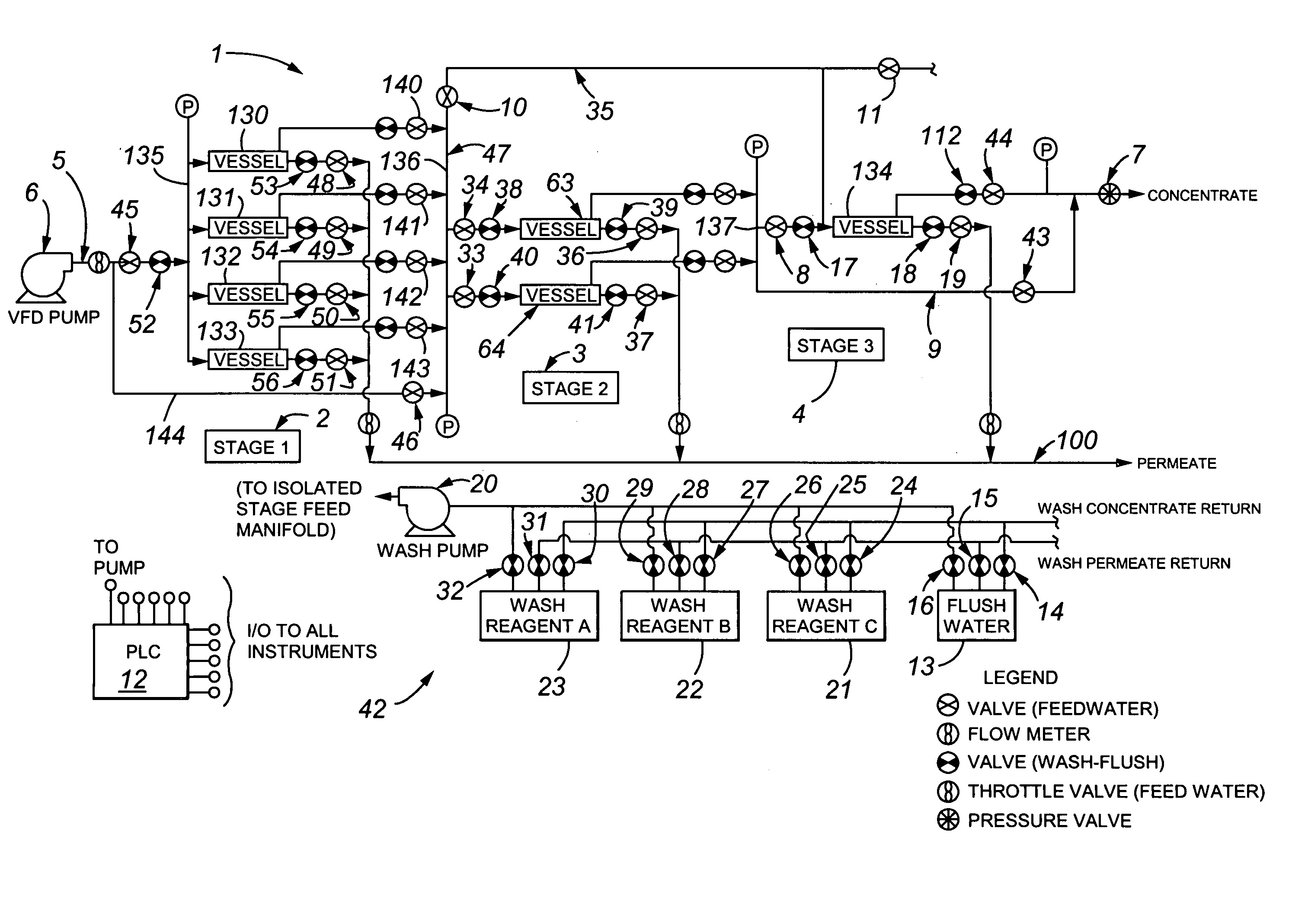
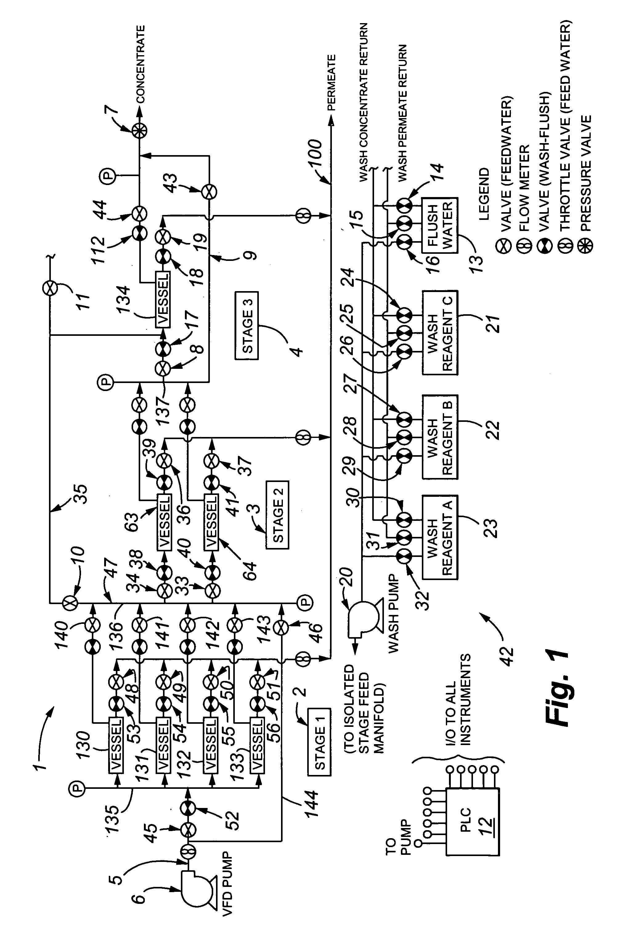
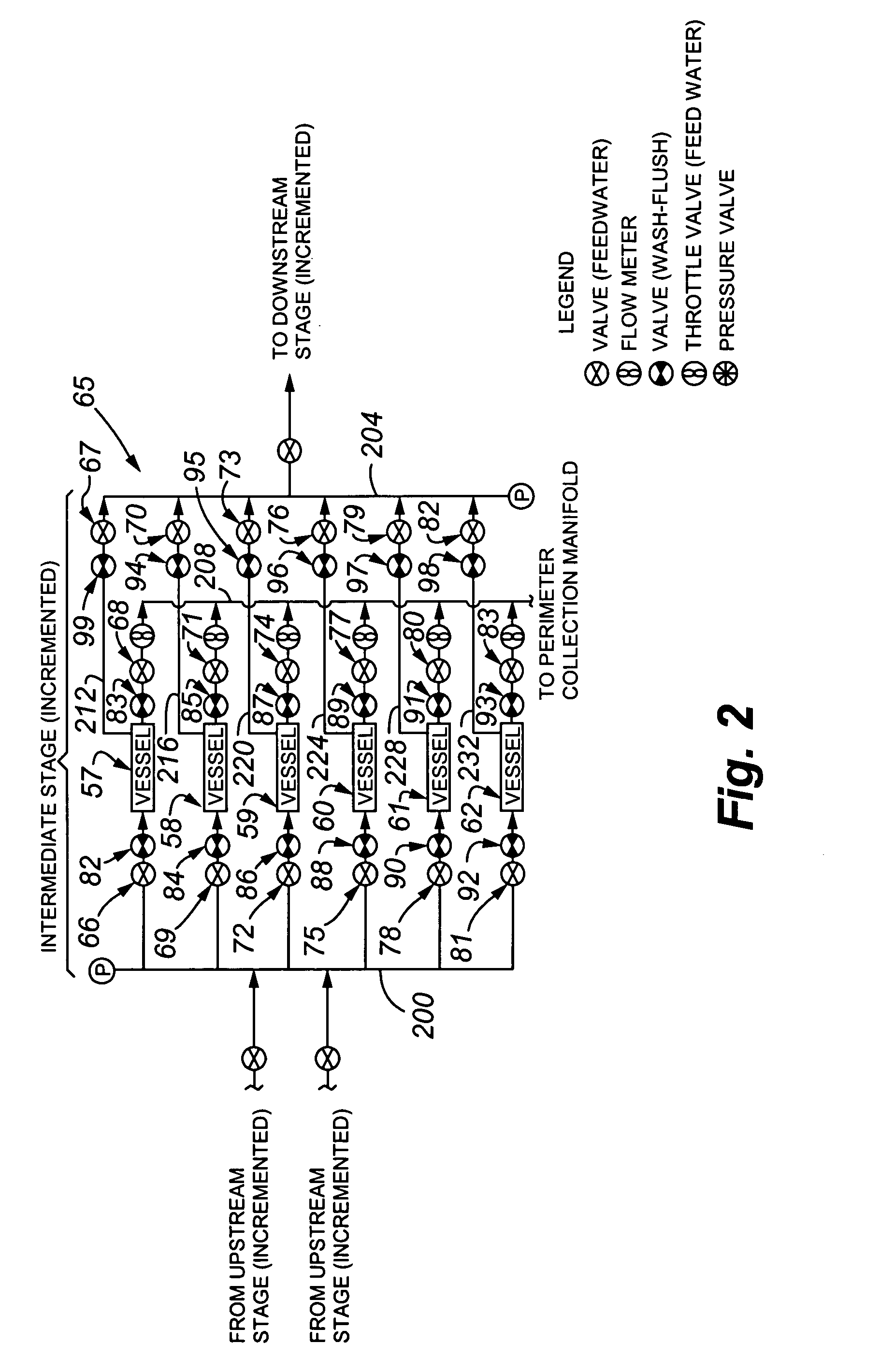
[0036] The present invention involves a tapered array membrane plant stage-by-stage or stage increment-by-stage increment pressure and permeate flow input / output (I / O) device monitoring system that, together with process-logic-control (PLC) programming, is effective in assigning a degree of fouling value to the stage or stage increment, as measured against a known standard pressure-permeate flow profile for the stage or stage increment. From the assigned degree of fouling of the stage or stage increment, a further process of the invention is the execution of an automated sequence of valve position changes to effect the diversion of feed water from the fouling affected stage of the plant and to pass the diverted water to the following stage of the plant for a stage wash process, or the parallel stage increments in a stage incremental wash process. Furthermore, a series of flush and wash solution valves are PLC re-set in...


PUM

PropertyMeasurementUnit
pressureaaaaaaaaaa
pressureaaaaaaaaaa
pressureaaaaaaaaaa

Abstract

A method is provided for the continuous production of treated waters using a staged, tapered array membrane plant by a process of process-logic-controlled (PLC) stage or stage increment isolation and removal from service, washing and return-to-service concurrent with the continued operation of all other stages and/or stage increments of the plant. Specifically, there are plant mounted input/output sensors that supply the PLC with the data required to identify the location and degree of “fouling” of the individual stages or stage increments of a tapered array membrane water treatment plant, where fouling is defined as a loss of water flow through a membrane surface at a given pressure when compared to a water flow standard for the surface. When a stage or stage increment of a plant is defined by this process to be “fouled,” the PLC commands the initiation of a sequence of automated valve openings and closings to a) remove the fouled stage or stage increment from feed water treatment service, b) to flush and wash the stage or stage increment, and c) to return the stage or stage increment to feed water treatment service. Optionally the PLC function can be extended to include the monitoring and control of ancillary valves and a variable-frequency-drive feed water pump to command the parts of a plant that remain on-line during the process of a stage or stage increment wash to continue to produce more, or less, or volumetrically identical amounts of membrane water treatment process permeate by combinations of valve re-settings, pump speed adjustments, and stage-to-stage intermediate water diversion.

Description

CROSS REFERENCE TO RELATED APPLICATION [0001] The present application claims the benefits of U.S. Provisional Application Ser. No. 60 / 505,480, filed Sep. 25, 2003, entitled “Membrane Plant On-Line Tail-End Wash Method”, which is incorporated herein by this reference.FIELD OF THE INVENTION [0002] The present invention relates generally to effluent treatment and specifically to removing emulsions and solids from membranes. BACKGROUND OF THE INVENTION [0003] With water shortages and environmental protection gaining global importance, membrane treatment of contaminated waters is becoming more widespread. Membranes can separate effectively suspended solids, entrained oils and greases, dissolved solids, and dissolved organics, and produce a low contaminant-content permeate water. Membranes can also conserve reagent-loaded matrix waters for recycle and recover valuable metals from metal-loaded waters. [0004] Membranes push feed water across leaves of membrane material with a permeate pocke...

Claims


Application Information

Patent Timeline
Patent Type & Authority Applications(United States)
IPC IPC(8): B01D61/02B01D61/14B01D65/02C02FC02F1/00C02F1/44
CPCB01D61/022C02F2303/16B01D61/142B01D61/22B01D65/02B01D2311/10B01D2311/14B01D2311/16B01D2313/48B01D2317/025B01D2317/027B01D2317/04B01D2321/02B01D2321/04B01D2321/16C02F1/44C02F2209/005B01D61/12B01D61/026B01D61/146
Inventor GREEN, DENNIS H.PIEGOLS, GEORGE D.LOMBARDI, JOHN A.HERBERT, GARY JOSEPH
Owner HW PROCESS TECH
Why Eureka
Try Eureka