Electric heater for thermal treatment furnace

a technology for heating furnaces and electric heaters, which is applied to furnace heating elements, furnaces, lighting and heating apparatuses, etc., can solve the problems of heavy heating element weight, inability to achieve fast heat-up or cool-down, and large heat capacity, and achieve high thermal stability

Inactive Publication Date: 2005-03-31
KOYO THERMO SYST CO LTD
View PDF6 Cites 23 Cited by
  • Summary
  • Abstract
  • Description
  • Claims
  • Application Information

AI Technical Summary

Benefits of technology

[0012] Further, in case where an inner thermal insulating material layer and an outer thermal insulating material layer jacket outside the main thermal insulation body, and where both connecting members are positioned between the inner thermal insulating material layer and the outer thermal insulating material layer, then, the connecting members can be isolated from high-temperature section of the heater, therefore, unfavorable influence of the parts of the parallel connections on temperature profile can be avoided, and their thermal distortion hardly occurs as well, which secures a construction with high thermal stability.
[0013] Furthermore, in the event where a sleeve or a cap is fitted on each end of respective resistance heat emitting portion and fixed by calking and / or welding, a number of open holes corresponding to the number of resistance heat emitting portions are opened in each connecting member, and where a sleeve or a cap is put through an open hole at a corresponding end, the sleeve or the cap and fringe of the open hole are welded, and where the resistance heat emitting portions, connecting members, and sleeves or caps are formed out of a same kind of material, then, the discontinuity of physical property, particularly discontinuities of metallurgy and thermal expansion coefficient can be avoided between the resistance heat emitting portion, the connecting member, and the sleeve or the cap, thus, even higher thermal stability can be achieved.
[0014] Additionally, in case where a number of parallel grooves not less than the number of the resistance heat emitting portions are formed at the inside surface of the main thermal insulation body, each resistance heat emitting portion is formed to a sinuous shape with an amplitude bigger than width of the groove, supported unitedly by the main thermal insulation body with both end portions of the amplitude plunging beyond the sidewalls of each corresponding groove into the main thermal insulation body, and extending from one groove over to next one at least, then, a construction is achievable which enables easy use of a light gauge metal wire for a heating element.

Problems solved by technology

Because a heavy gauge metal wire is used in the aforementioned conventional electric heater, weight of the heating element is heavy, then, it has a large heat capacity.
A problem with such a heater is that a fast heat-up or cool-down cannot be achieved.
Besides, energy loss per heat cycle is large.
However, since there is a difference in current specification between the former and the latter types of heater, the latter type heater cannot be employed directly to an existing heat treating equipment where the former type heaters have been installed.

Method used


Image

  • Electric heater for thermal treatment furnace
  • Electric heater for thermal treatment furnace
  • Electric heater for thermal treatment furnace

Examples


Embodiment Construction

[0024] An embodiment of the present invention is explained in the following making reference to the drawings.

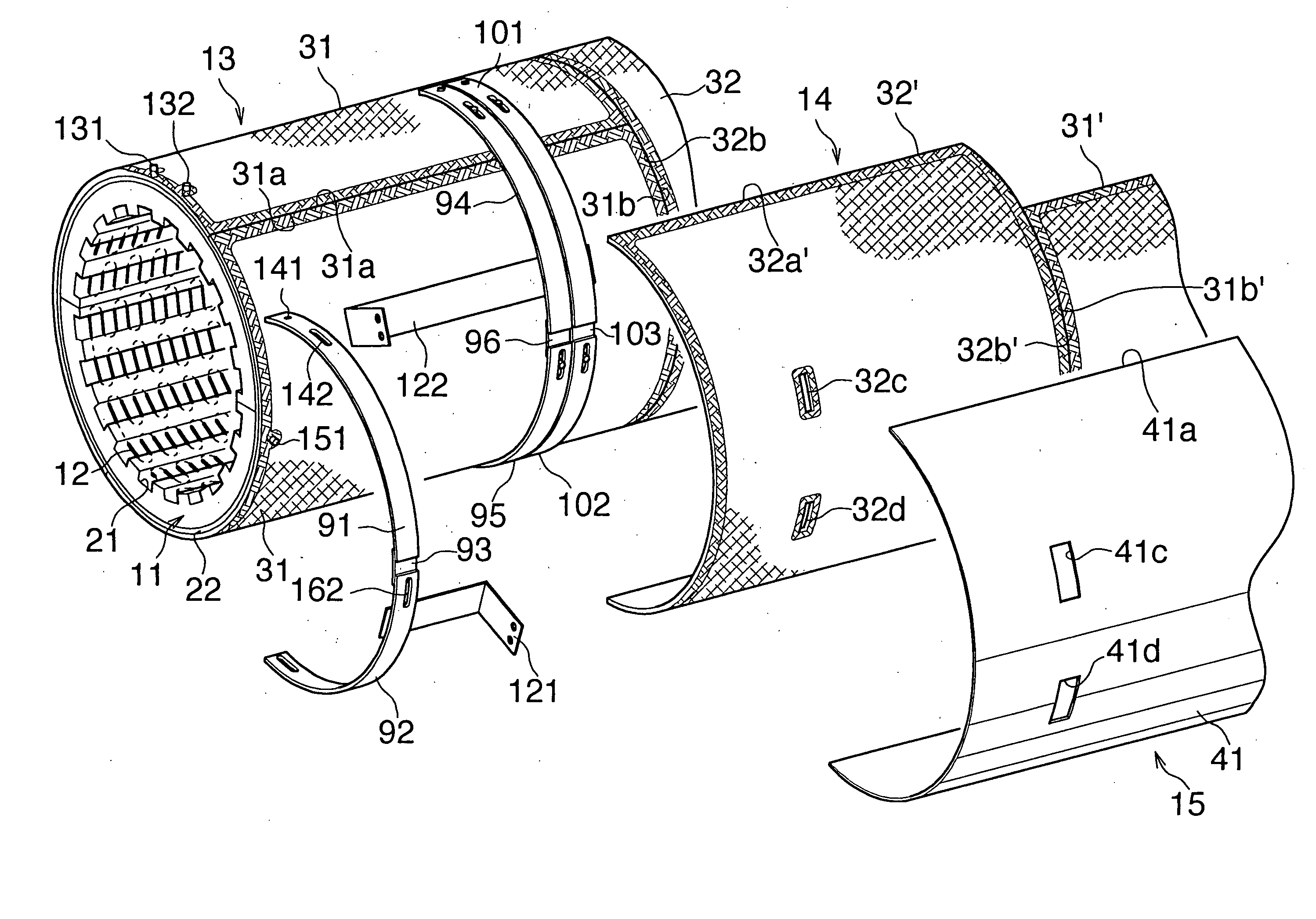
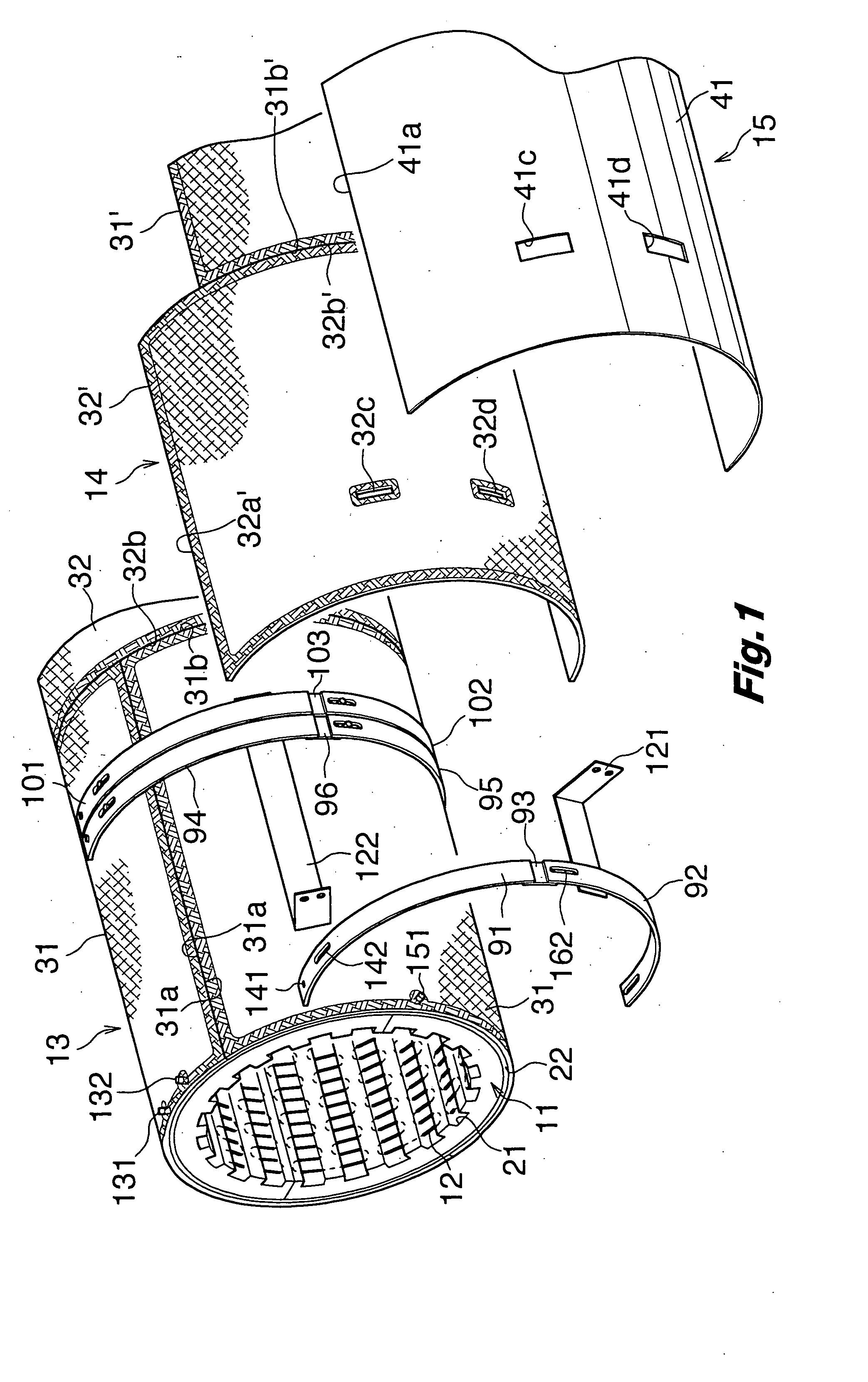
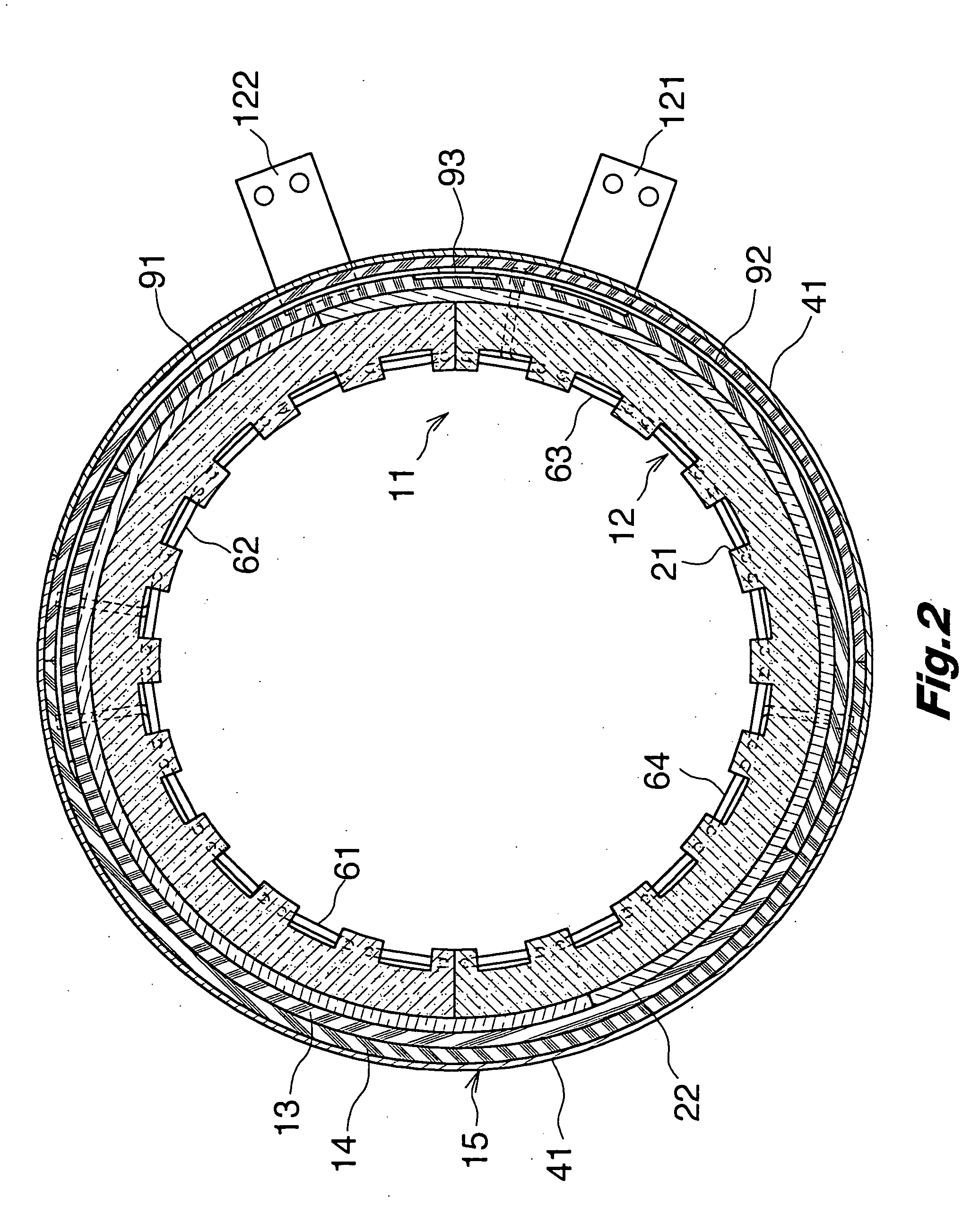
[0025] Referring to FIGS. 1 and 2, an electric heater comprises a cylindrical main thermal insulation body (11), a heating element (12) installed at an internal circumferential surface of the main thermal insulation body (11), layers of inner thermal insulating material (13) and outer thermal insulating material (14) jacketing thereof intervened by a flexible mat as a buffer (22) consisting of ceramic fiber covering the external circumferential surface of the main thermal insulation body (11), and a metal shell (15) mantling the contour of the outer thermal insulating material layer (14).

[0026] With reference to FIG. 4, the electric heater is, from left to right successively, allotted for left zone (L), center zone (C) and right zone (R). In FIG. 1, only the left zone (L) and part of the center zone (C) are shown.

[0027] The main thermal insulation body (11) is vacuum forme...


PUM


Abstract

A heating element (12) made of metal wire is installed at an internal circumferential surface of a cylindrical main thermal insulation body (11) of an electric heater according to the present invention. The heating element (12) comprises a plurality of resistance heat emitting portions (61)-(64)(71)-(74)(81)-(84) as segments along its length direction. The resistance heat emitting portions (61)-(64)(71)-(74)(81)-(84) are connected in parallel.

Description

BACKGROUND ART [0001] The present invention relates to an electric heater for heat treating furnaces, and, particularly, it is suitably used for heat treating equipments to perform, for example, heat treatments such as oxidation, diffusion, and / or CVD of semiconductor wafers. [0002] Conventionally, an electric heater is known which uses a heating element installed at an internal circumferential surface of its cylindrically shaped main thermal insulation body, the heating element being formed to coil shape out of a metal wire referred to as “heavy gauge” whose diameter is 7 to 10 mm. [0003] Then, as a replacement to the above-mentioned electric heater, the present applicant proposed previously an electric heater which is disclosed by a Japanese Patent Application Publication Number 2001-267261. This utilizes a metal wire referred to as “light gauge” of which diameter is 1 to 3 mm, and a plurality of parallel grooves are formed at an internal circumferential surface of its main therma...

Claims


Application Information

Patent Timeline
Patent Type & Authority Applications(United States)
IPC IPC(8): F27D1/00F27D1/04F27D11/02F27D99/00H01L21/00H01L21/22H05B3/62H05B3/64H05B3/66H05B6/64
CPCF27D1/0036F27D2001/047H05B3/66H05B3/64F27D2099/0008F27D11/02
Inventor UEMORI, SUSUMUAITANI, TAKASHI
Owner KOYO THERMO SYST CO LTD
Why Eureka
Try Eureka