High efficiency combination direct/indirect water heater

a water heater and high efficiency technology, applied in the direction of water heaters, stationary conduit assemblies, steam generation using hot heat carriers, etc., can solve the problems of low heating efficiency of indirect heating systems, time-consuming and therefore costly, and high cost of the former, so as to facilitate unhindered gas venting and prevent back pressure

Inactive Publication Date: 2005-04-07
QUIKWATER
View PDF36 Cites 6 Cited by
  • Summary
  • Abstract
  • Description
  • Claims
  • Application Information

AI Technical Summary

Benefits of technology

[0011] It is a further object of the present invention to provide a high efficiency combination direct / indirect water heater that enhances indirect heat transfer. A feature of an embodiment of the present invention is an extended gas-carrying manifold submerged in the water to be heated. In a specific embodiment of the present invention the gas-carrying manifold is encased in a sleeve of water to define a pre-configured annular space. Another feature of the present invention are radially protruding fins from the manifold. An advantage of the present invention is that it ensures that the water to be heated is in constant and close thermal contact with the heated gases during the initial water input mode and in the storage mode, thereby enhancing heat transfer efficiency.
[0012] Another object of the present invention is to provide a high efficiency combination direct / indirect water heater that allows unimpeded escape of the heated gases from a heat exchange manifold. A feature of the present invention is that the manifold terminates with a cap structure which prevents water blockage of the heated gas at the egress point. An advantage of the present invention is that the means of egress facilitates unhindered venting of gas and prevents back pressure from occurring at the gas egress point.
[0013] Yet another object of the present invention is to provide a high efficiency combination direct / indirect water heater having a water reservoir configuration which prevents combustion gas build-up. A feature of the present invention is the positioning of a combustion gas point of egress adjacent to a water surface point in a vertical riser. An advantage of the present invention is the elimination of any gas head spaces and therefore of the build-up of high gas pressure and the accumulation of high temperature gas between the water level and a solid surface of the heater.
[0014] Briefly, the invention provides a water heater comprising: a tower with a cold water inlet conduit causing water to fall through the tower and into a hot water collection tank in communication with the tower; a hot gas manifold adapted to receive hot gases and positioned in the tank so as to be at least partially submerged below the water surface; and a means of gas egress attached to the hot gas manifold and positioned above the water surface, the gas egress means configured to prevent the water falling through the tower from blocking gas egress from the manifold. In an alternative embodiment, the water collection tank surrounding said gas manifold forms an annular space adapted to receive water, the annular space configured to maximize thermal exchange between the manifold and the water residing in the annular space.

Problems solved by technology

While direct water heaters are more efficient than indirect-heating configurations, the costs of the former are formidable.
For example, the fabrication of housings for the combustion chamber of such units is time consuming, and therefore costly.
The heating efficiency of indirect heating systems is low inasmuch as such systems loose heat through the egress of hot combustion gases.
The heating efficiencies of direct systems also can be low in situations where either the combustion gas temperature or the incoming water temperature is too high to facilitate condensation of all the water vapor in the heating zone.
Instead, water vapor exits the system, resulting in heat loss.
Finally, water-storage tank configurations in typical direct heating systems result in a build-up of vapor pressure above the water level in the tank (i.e., the “head space”) resulting in operating instabilities and further heat losses.

Method used


Image

  • High efficiency combination direct/indirect water heater
  • High efficiency combination direct/indirect water heater
  • High efficiency combination direct/indirect water heater

Examples


Embodiment Construction

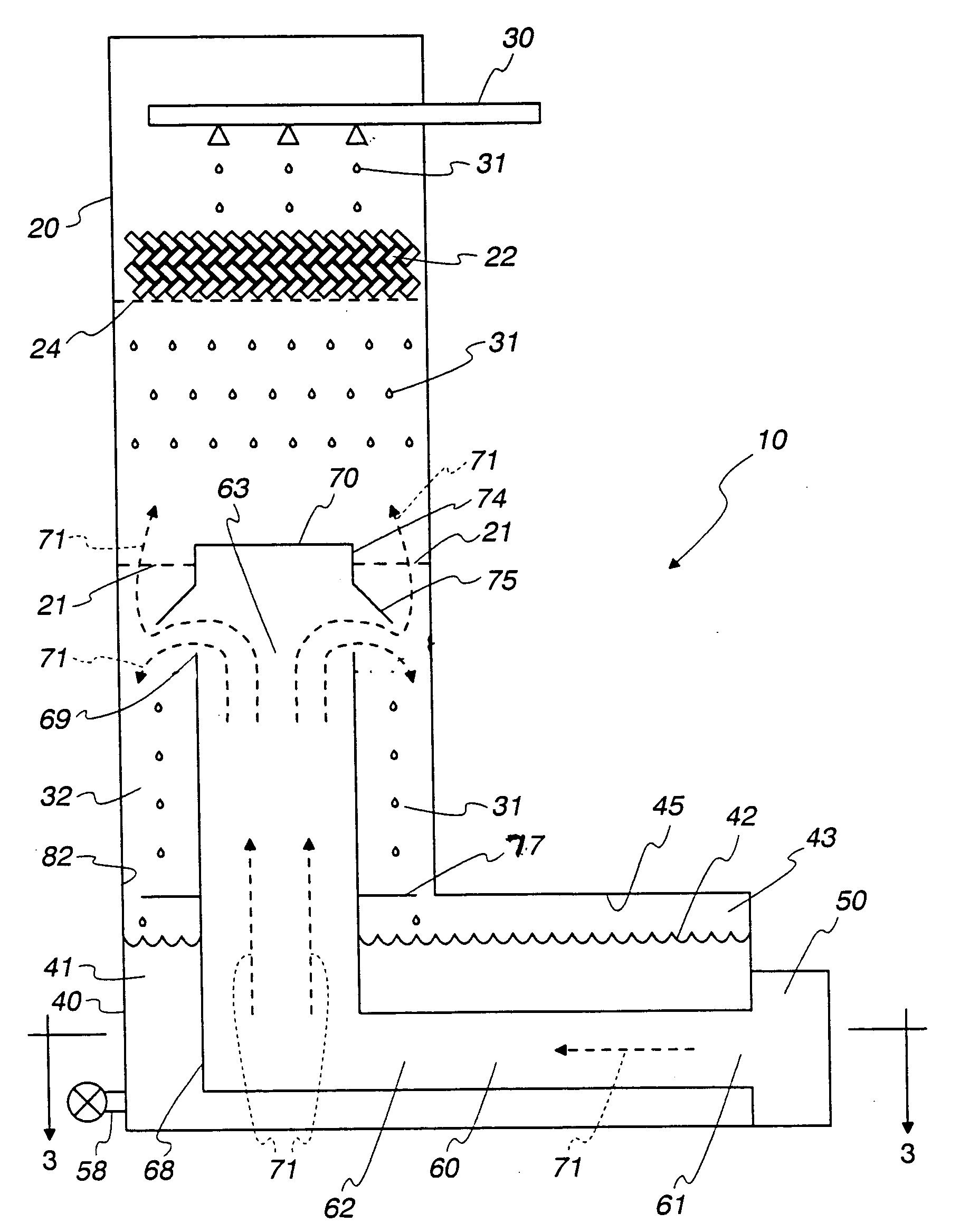
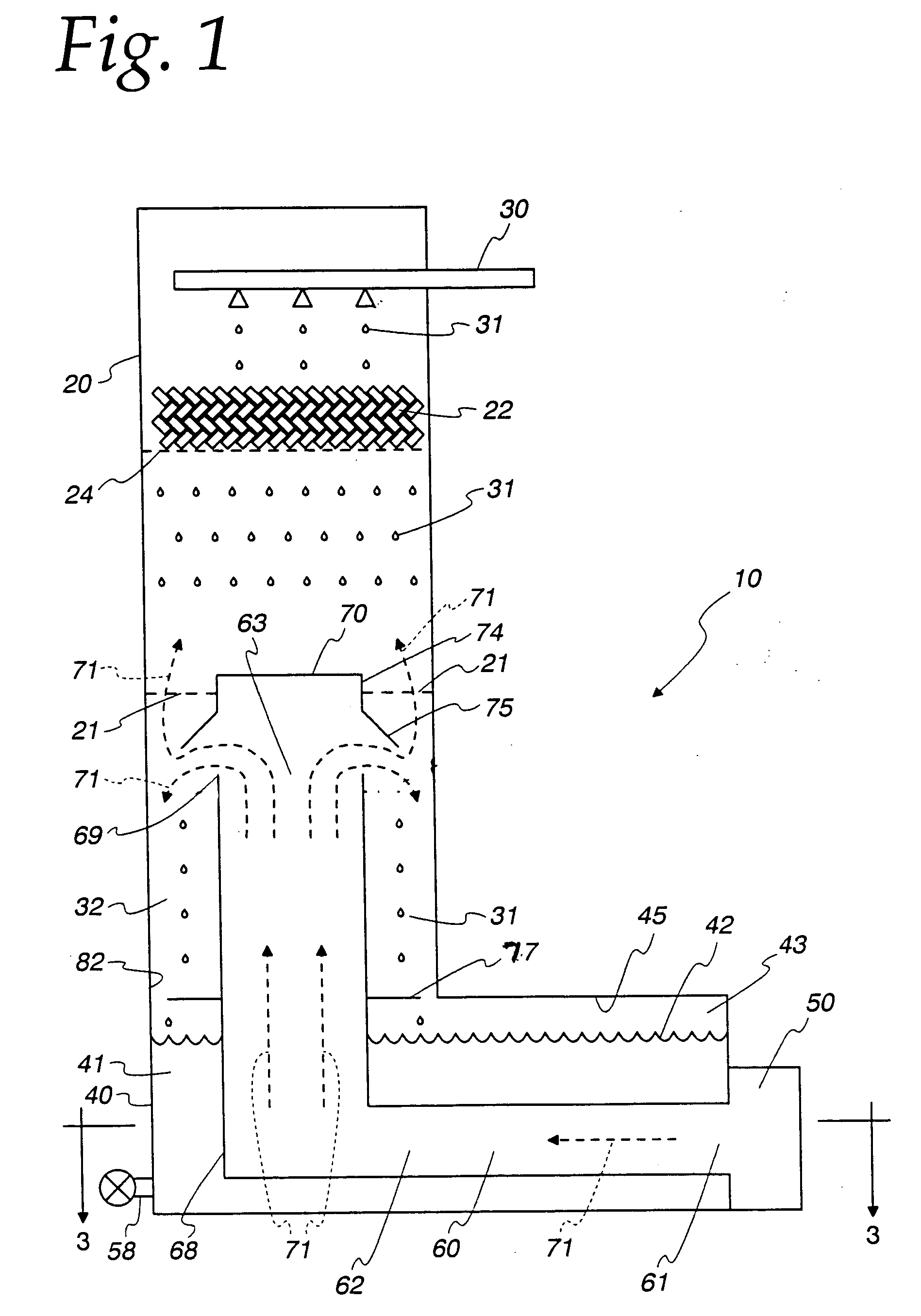
[0029] The present invention provides a high efficiency combination direct / indirect heater that facilitates both direct and indirect heat transfer to a liquid. For the sake of simplicity, it will be assumed throughout this specification that the liquid being heated is water. A salient feature of the invention is the immersion of a heat transfer surface, such as a combustion gas manifold, in already heated water, thereby enhancing efficiencies.

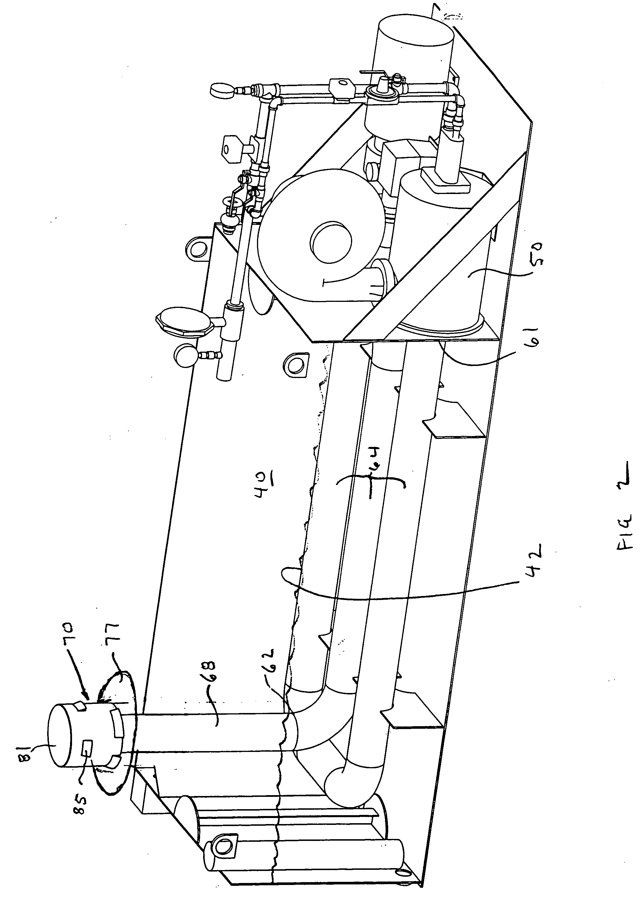
[0030] As shown in FIG. 1, the combination direct / indirect water heater, generally designated as numeral 10 is comprised of five main components: a vertical riser 20 (often called “tower”), a cold water supply inlet 30, a hot water reservoir 40, a fuel burner 50, a hot gas inlet conduit or manifold 60 that is nearly fully submerged in the reservoir 40, and a means for water egress 58. FIG. 2 is a perspective view of the invented combination direct / indirect water heater, without the tower.

[0031] A water supply and distribution means 30 distrib...


PUM


Abstract

A combination direct / indirect liquid heating heater comprises a tower, a cold water inlet conduit causing water to fall in said tower, a hot water reservoir in communication with said tower, a gas burner, a hot gas inlet manifold encased in the reservoir and, by means of a vertical section, directing the gas into the tower. The hot gas manifold vertical section is capped by a cap impeding water flow into the manifold. Also, the vertical section comprises a baffle impeding gas flow from the tower into the reservoir.

Description

BACKGROUND OF THE INVENTION [0001] 1. Field of the Invention [0002] The present invention relates to the field of water heaters and, more particularly, the present invention relates to high efficiency devices which heat water using thermal conduction and also via direct contact of the water with combustion gases. [0003] 2. Description of the Prior Art [0004] Direct heating of water by combustion gases is known. U.S. Pat. No. 6,089,223 awarded to Jasper et al. on Jul. 18, 2000, and assigned to the instant assignee teaches a heater whereby falling water contacts hot combustion gases. [0005] While direct water heaters are more efficient than indirect-heating configurations, the costs of the former are formidable. For example, the fabrication of housings for the combustion chamber of such units is time consuming, and therefore costly. Also, water switches and additional spray nozzles are necessary to assure adequate cooling of the housings and also of the combustion gases, respectively....

Claims


Application Information

Patent Timeline
Patent Type & Authority Applications(United States)
IPC IPC(8): F24H1/10F28C3/06F28D1/02
CPCF24H1/107F28D1/0213F28C3/06
Inventor WEBER, FRANK WILLIAMPRUITT, JEFFREY KENTWALKER, BRIAN KEITH
Owner QUIKWATER
Why Eureka
Try Eureka