
Method of making membrane electrode assemblies

a technology of membrane electrodes and electrode assemblies, which is applied in the direction of cell components, electrochemical generators, coatings, etc., can solve the problems of greater cost associated with fuel cell manufacture than competitive power generation alternatives, and achieve the effect of sufficient structural integrity and convenient reus

Inactive Publication Date: 2005-04-07
GM GLOBAL TECH OPERATIONS LLC
View PDF14 Cites 31 Cited by
  • Summary
  • Abstract
  • Description
  • Claims
  • Application Information

AI Technical Summary

Benefits of technology

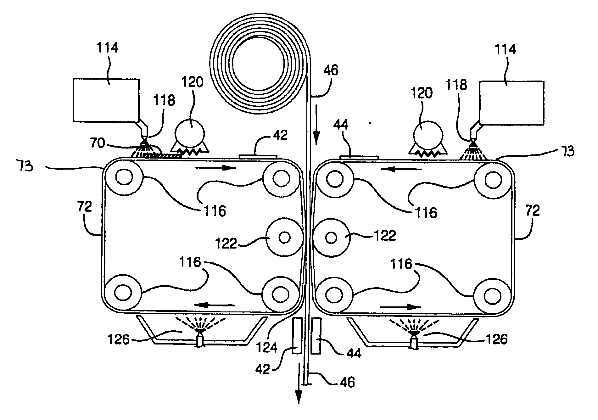
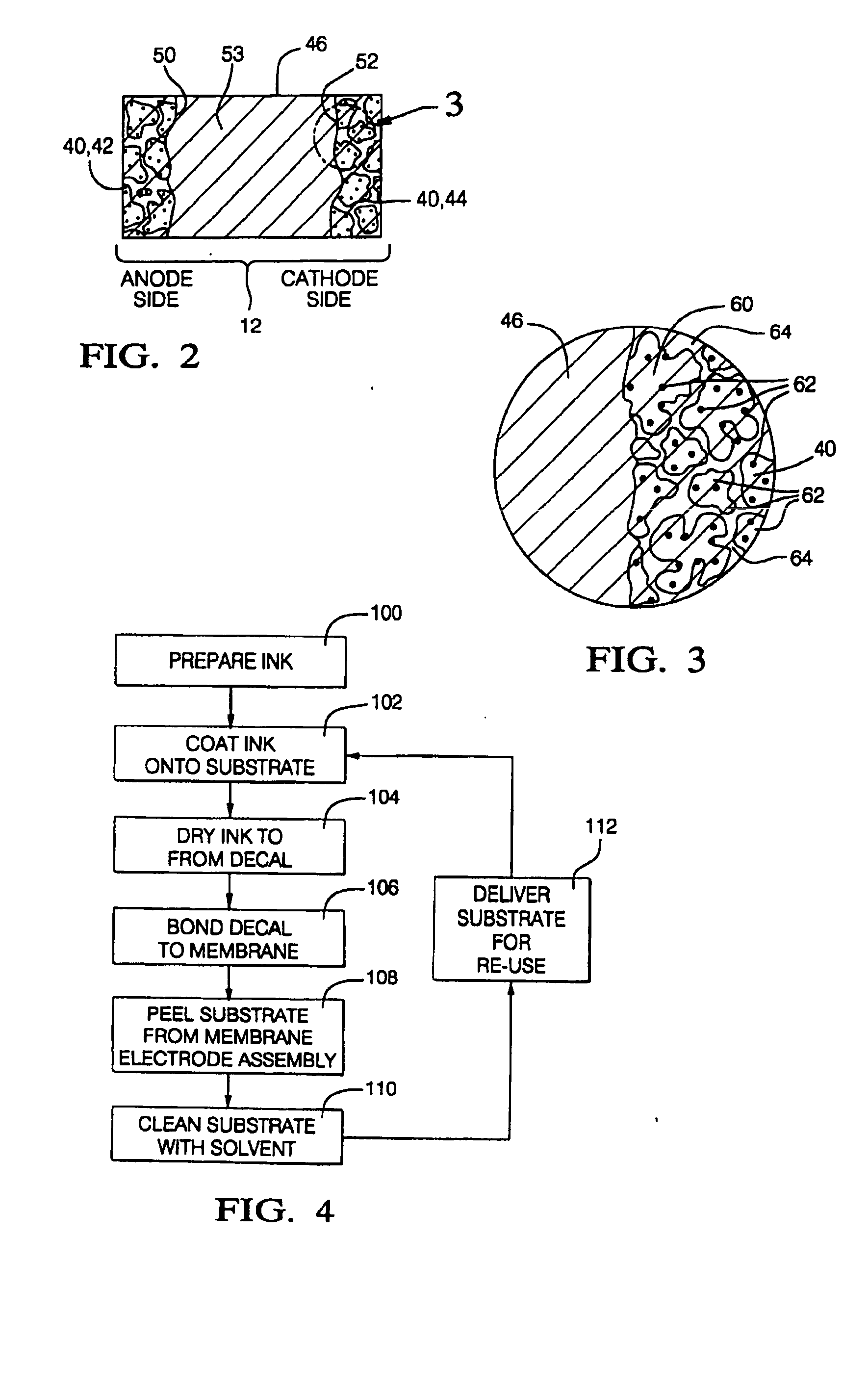
The present invention provides a method for making a membrane electrode assembly. The method involves applying a slurry containing an ionically conductive material, an electrically conductive material, a catalyst, and a high boiling point casting solvent to a non-porous polymeric substrate, such as ethylene tetrafluoroethylene or polyimide, and removing the solvent to form a dried electrode film on the substrate. The dried electrode is then bonded to a membrane and the substrate is separated. The substrate can be reused. The invention also provides a continuous process for making the membrane electrode assembly by applying the slurry to discrete regions on a continuous strip of non-porous polymeric substrate, bonding the membrane to the substrate, and cleaning the substrate. The technical effects of the invention include improved efficiency and reduced costs for making membrane electrode assemblies.

Problems solved by technology

The costs associated with fuel cell manufacture are greater than competitive power generation alternatives, partly because of the cost of preparing such electrodes and MEAs.

Method used


Image

  • Method of making membrane electrode assemblies
  • Method of making membrane electrode assemblies
  • Method of making membrane electrode assemblies

Examples


Embodiment Construction

[0019] The following description of the preferred embodiments is merely exemplary in nature and is in no way intended to limit the invention, its application, or uses. For example, although the invention is described herein with reference to a fuel cell, it is applicable to electrochemical cells generally.

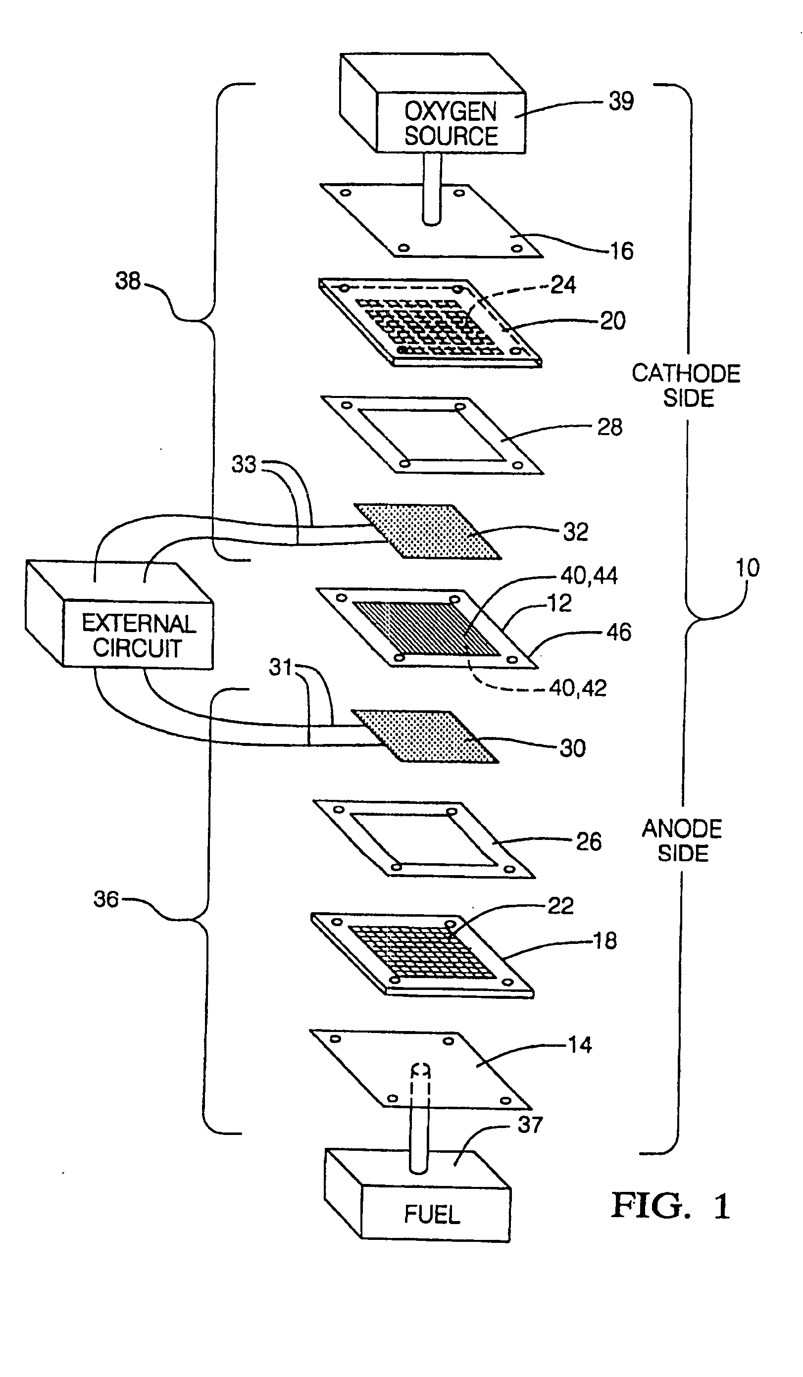
[0020] The present invention contemplates forming electrodes and membrane electrode assemblies for use in fuel cells. Before describing the invention in detail, it is useful to understand the basic elements of a fuel cell and the components of the membrane electrode assembly. Referring to FIG. 1, an electrochemical cell 10 with a membrane electrode assembly 12 incorporated therein is shown in pictorial unassembled form. The illustrated electrochemical cell 10 is constructed as a fuel cell. Electrochemical cell 10 comprises stainless steel or aluminum endplates 14, 16, bipolar gas diffusion elements or plates 18,20 with a plurality of channels 22, 24 to facilitate gas distribution,...


PUM

PropertyMeasurementUnit
thicknessaaaaaaaaaa
surface energyaaaaaaaaaa
boiling pointaaaaaaaaaa

Abstract

A method of making a membrane electrode assembly is provided. The method includes providing a non-porous polymeric substrate which has sufficient structural integrity and elastic deformation such that no significant deformations occur during processing to facilitate reuse. The substrate is optionally formed into a loop for continuous processing. A slurry is formed which includes an ionically conductive material, an electrically conductive material, a catalyst, and a high boiling point solvent. The slurry is applied onto the non-porous polymeric substrate, for example, in a pattern of discrete regions. The slurry is dried to form decals. The decals are bonded to a membrane and then the substrate is peeled from the decal in a substantially undamaged condition so that it may be reused.

Description

FIELD OF THE INVENTION [0001] The present invention relates to PEM / SPE fuel cells, and more particularly to a method of making electrodes and membrane electrode assemblies. BACKGROUND OF THE INVENTION [0002] Electrochemical cells are desirable for various applications, particularly when operated as fuel cells. Fuel cells have been proposed for many applications including electrical vehicular power plants to replace internal combustion engines. One fuel cell design uses a solid polymer electrolyte (SPE) membrane or proton exchange membrane (PEM), to provide ion exchange between the anode and cathode. Gaseous and liquid fuels may be used within fuel cells. Examples include hydrogen and methanol, with hydrogen being favored. Hydrogen is supplied as a reductant to the fuel cell's anode. Oxygen (as air) is an oxidant and is supplied to the cell's cathode. The electrodes are formed of electrode porous conductive materials which facilitate the electrochemical reactions in the cell. Further...

Claims


Application Information

Patent Timeline
Patent Type & Authority Applications(United States)
IPC IPC(8): B05D5/12B32B7/00B32B7/08B44C1/00B44C1/165H01MH01M4/88H01M4/90H01M4/92H01M4/94H01M4/96H01M8/10
CPCH01M4/881H01M4/8814H01M4/8828H01M4/8835Y02E60/50H01M4/8857H01M4/926H01M2008/1095Y02E60/523H01M4/8839
Inventor YAN, SUSAN G.SCOZZAFAVA, MICHAEL
Owner GM GLOBAL TECH OPERATIONS LLC
Learn More