Process and injection apparatus for reducing the concentration of NOX pollutants in an effluent
Inactive Publication Date: 2005-04-07
WOJICHOWSKI DAVID LEE
View PDF1 Cites 15 Cited by
Summary
Abstract
Description
Claims
Application Information
AI Technical Summary
This helps you quickly interpret patents by identifying the three key elements:
Problems solved by technology
Method used
Benefits of technology
[0017] The object of the current invention is to provide an improvement to the Selective Non-Catalytic Reduction system of nitrogen oxide emissions from stationary combustion sources. In particular, the invention discloses an injector apparatus which mixes an atomization medium with an SNCR reagent in a jet pump
Problems solved by technology
In addition, carbonaceous fuels contain finite quantities of nitrogen, a portion of which oxidizes to form additional nitrogen oxides.
Nitrogen oxides, especially NO, are troublesome pollutants which are found in the combustion effluent streams of large utility boilers when fired as discussed above, and comprise a major irritant in smog.
Unfortunately, the high temperatures and relatively hostile environment within a utility boiler make most common metho
Method used
Image
Click on the blue label to locate the original text in one second.
Reading with bidirectional positioning of images and text.
Examples
Embodiment Construction
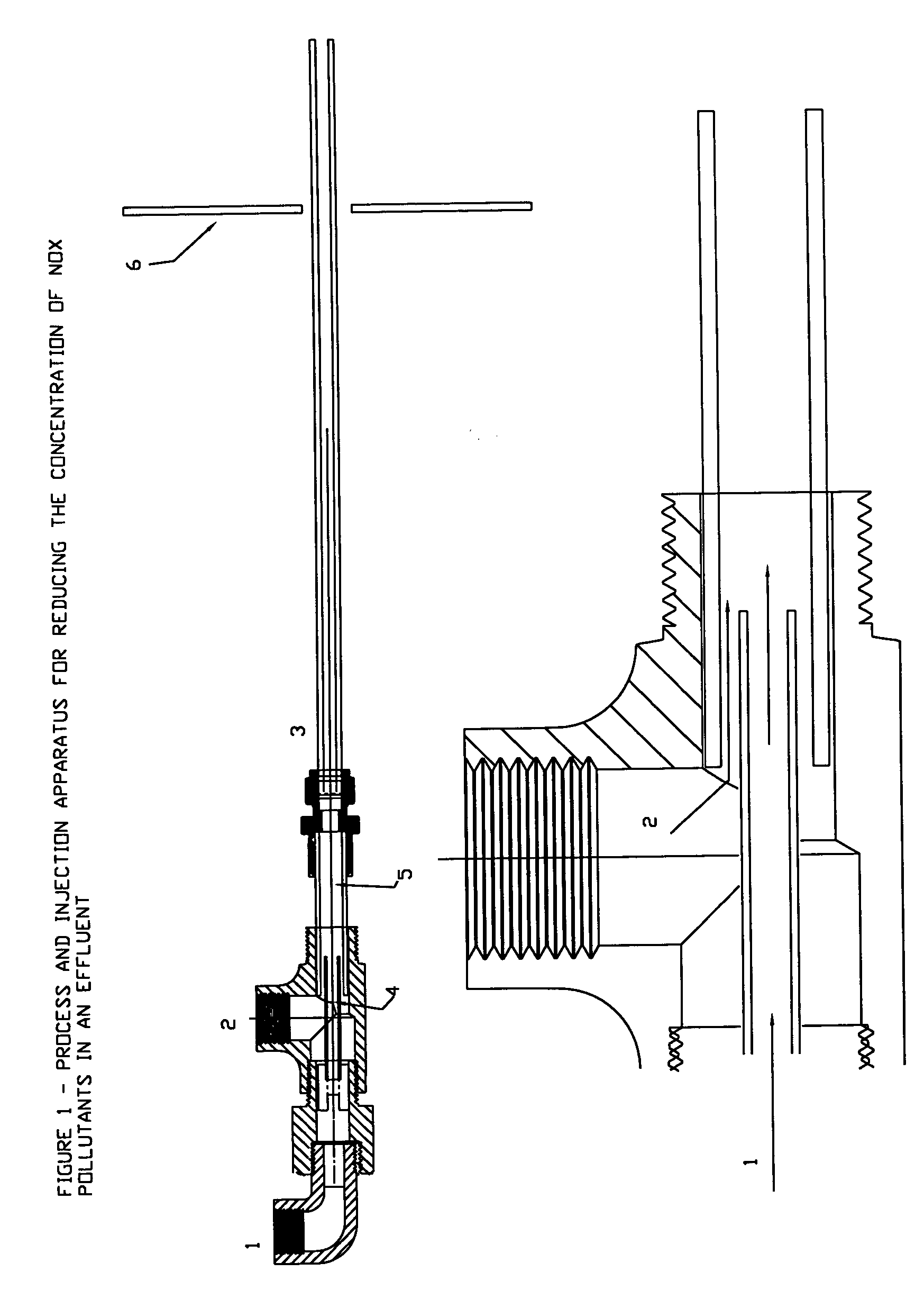
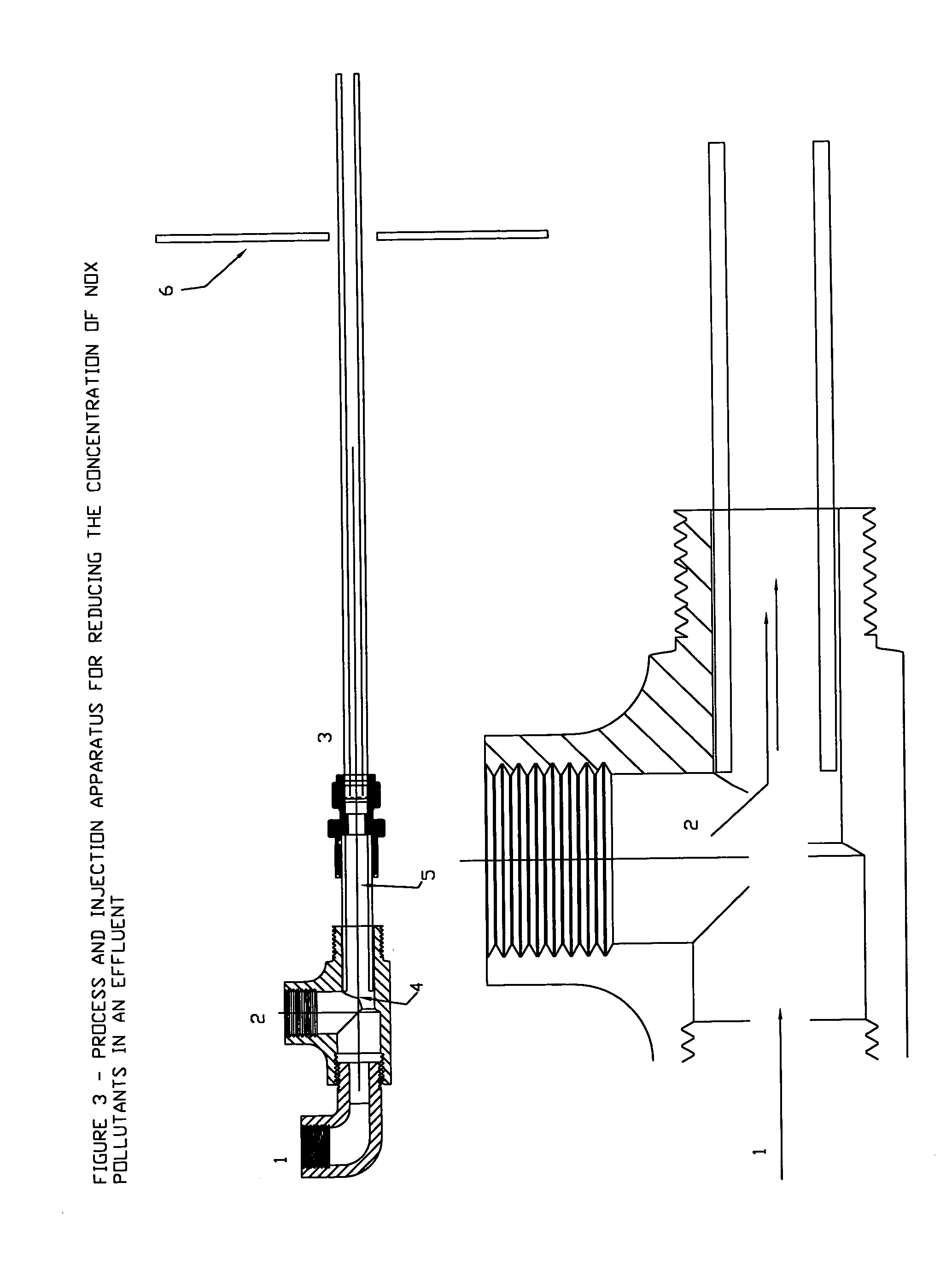
[0021]FIG. 1 illustrates one version of the injector apparatus in which an atomization medium is introduced to the assembly in the axial direction, item 1. The atomization medium travels through a small inner conduit, terminating coaxially and concentrically inside a larger mixing chamber, item 5. The SNCR reagent, either liquid or gaseous is introduced to the mixing chamber via the annular opening formed between the atomization medium conduit and the mixing chamber. The orientation of the two fluid streams allows the transfer of energy and momentum from the atomization medium to the SNCR reagent. The mixed fluids are conveyed past the boiler wall (item 6) via a single walled atomization conduit (item 3). The atomization conduit extends into the combustion effluent and produces a jet spray which mixes the SNCR reagent with the combustion effluent.
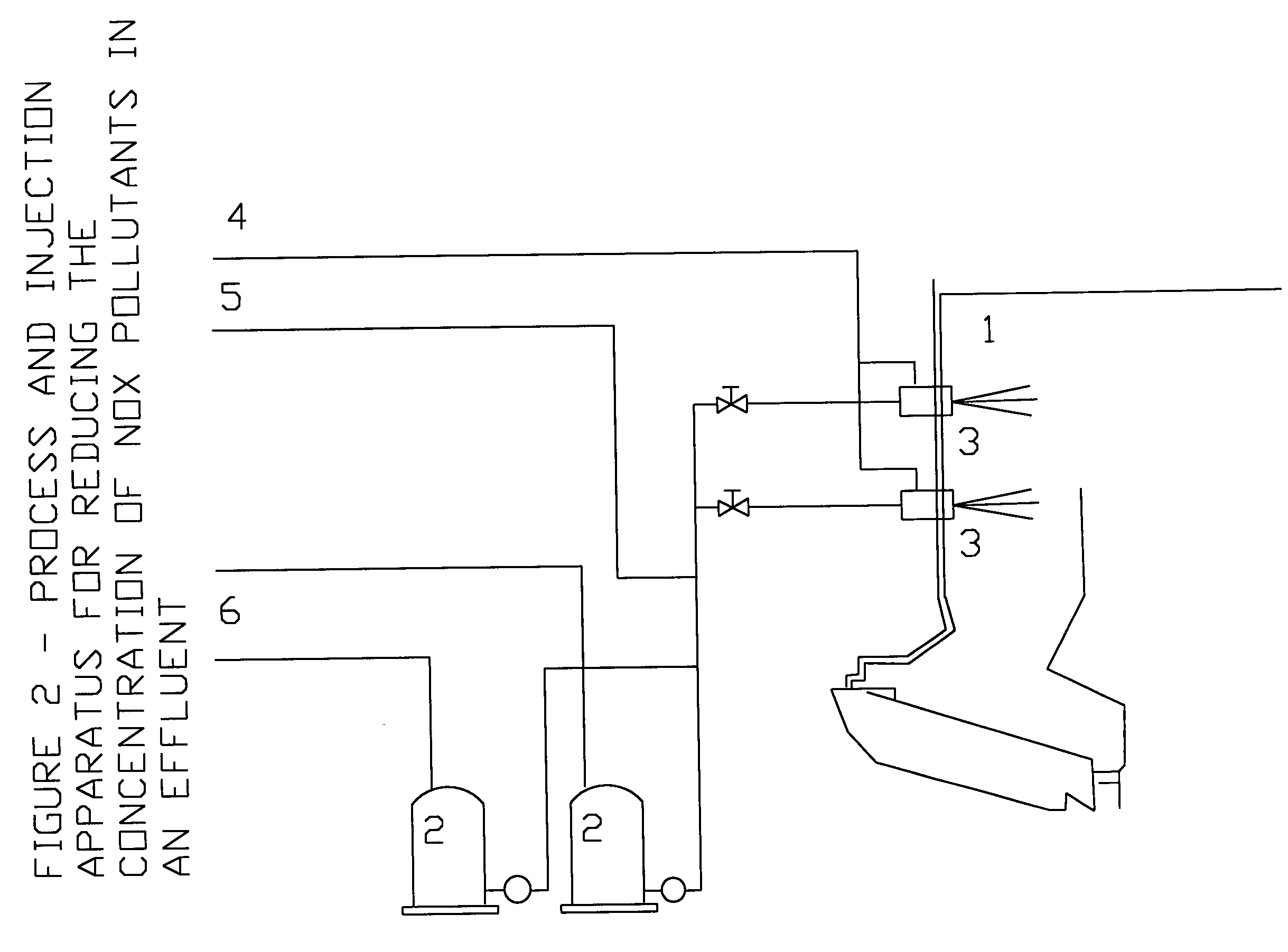
[0022]FIG. 2 is a schematic diagram of the overall SNCR process. The combustor, item 1, produces a high temperature effluent into which S...
PUM
Abstract
This invention relates to pollution control requirements for fossil fuel burning facilities, such as power plants, incinerators and cement kilns, and more particularity, to improved methods of atomizing an SNCR reagent into the combustion effluent therof.
Description
CROSS-REFERENCE TO RELATED APPLICATIONS [0001]3,900,554August 1975LYON4,208,386June 1980ARAND4,842,834June 1989BURTON4,915,036April 1990DEVITA5,315,941MAY 1994VETTERICK ET AL5,252,298October 1993JONES5,342,592August 1994PETER-HOBLYN ET AL5,478,542December 1995CHAWLA6,048,510April 2000ZAUDEREROTHER REFERENCES [0002] Perry's Chemical Engineer's Handbook, 5th Edition. STATEMENT REGARDING FEDERAL SPONSORSHIP [0003] No portion of this invention was made under government sponsored research or development. BACKGROUND OF THE INVENTION [0004] The present invention relates to the reduction of pollutants, such as nitrogen oxides in an effluent, from the combustion effluent of a carbonaceous fuel. More particularly, this invention relates to a process and apparatus to accomplish this. [0005] High temperatures, as well as hot spots of higher temperatures, cause the production of thermal NOX, the temperatures being so high that free radicals of oxygen and nitrogen are formed and chemically combin...
Claims
Application Information
Patent Timeline
Application Date:The date an application was filed.
Publication Date:The date a patent or application was officially published.
First Publication Date:The earliest publication date of a patent with the same application number.
Issue Date:Publication date of the patent grant document.
PCT Entry Date:The Entry date of PCT National Phase.
Estimated Expiry Date:The statutory expiry date of a patent right according to the Patent Law, and it is the longest term of protection that the patent right can achieve without the termination of the patent right due to other reasons(Term extension factor has been taken into account ).
Invalid Date:Actual expiry date is based on effective date or publication date of legal transaction data of invalid patent.