Hydrogen production and water recovery system for a fuel cell

a fuel cell and water recovery technology, applied in the field of fuel cell systems, can solve the problems of high cost, high cost, and/or bulky storage systems, and achieve the effects of improving water neutrality, reducing the number of components in the system, and increasing the efficiency of the system

Inactive Publication Date: 2005-04-07
HYDROGENICS CORP
View PDF0 Cites 38 Cited by
  • Summary
  • Abstract
  • Description
  • Claims
  • Application Information

AI Technical Summary

Benefits of technology

[0040] The metal hydride hydrogen storage and water recovery system according to the present invention provides a safe and compact fuel cell system, eliminating the need for bulky, highly pressurized storage devices and reducing the number of components in the system. Moreover, the present invention utilizes characteristics of the metal hydride and the readily available water in its vicinity, resulting in increased system efficiency. In a regenerative embodiment, the present invention significantly improves the water neutrality thereof by utilizing the reversible characteristic of the metal hydride hydrogen absorption process.

Problems solved by technology

However, these fuel cells require external supply and storage devices for hydrogen.
Hydrogen can be difficult to store and handle, particularly in non-stationary applications.
However, such storage systems tend to be hazardous, dangerous, expensive and / or bulky.
The system disclosed in U.S. Pat. No. 5,900,330 does not fully utilize heat and water from the fuel cell reaction.
It requires frequent refilling of water from an external source to continue its operation, making the system bulky and inefficient, especially for automotive applications.
For fuel cells, especially PEM fuel cells, an important issue to ensure proper performance of the fuel cells is humidification of process gases.
Nonetheless, it is possible for the flow of gas across the cathode side to be sufficient to remove this water, resulting in drying out on the cathode side as well.
However, this water recovery system is complicated, requiring a large number of components and fails to utilize the hydrogen storage characteristic of the metal hydride materials and heat of the condensed water for increasing the hydrogen production of the hydride bed.

Method used


Image

  • Hydrogen production and water recovery system for a fuel cell
  • Hydrogen production and water recovery system for a fuel cell
  • Hydrogen production and water recovery system for a fuel cell

Examples


first embodiment

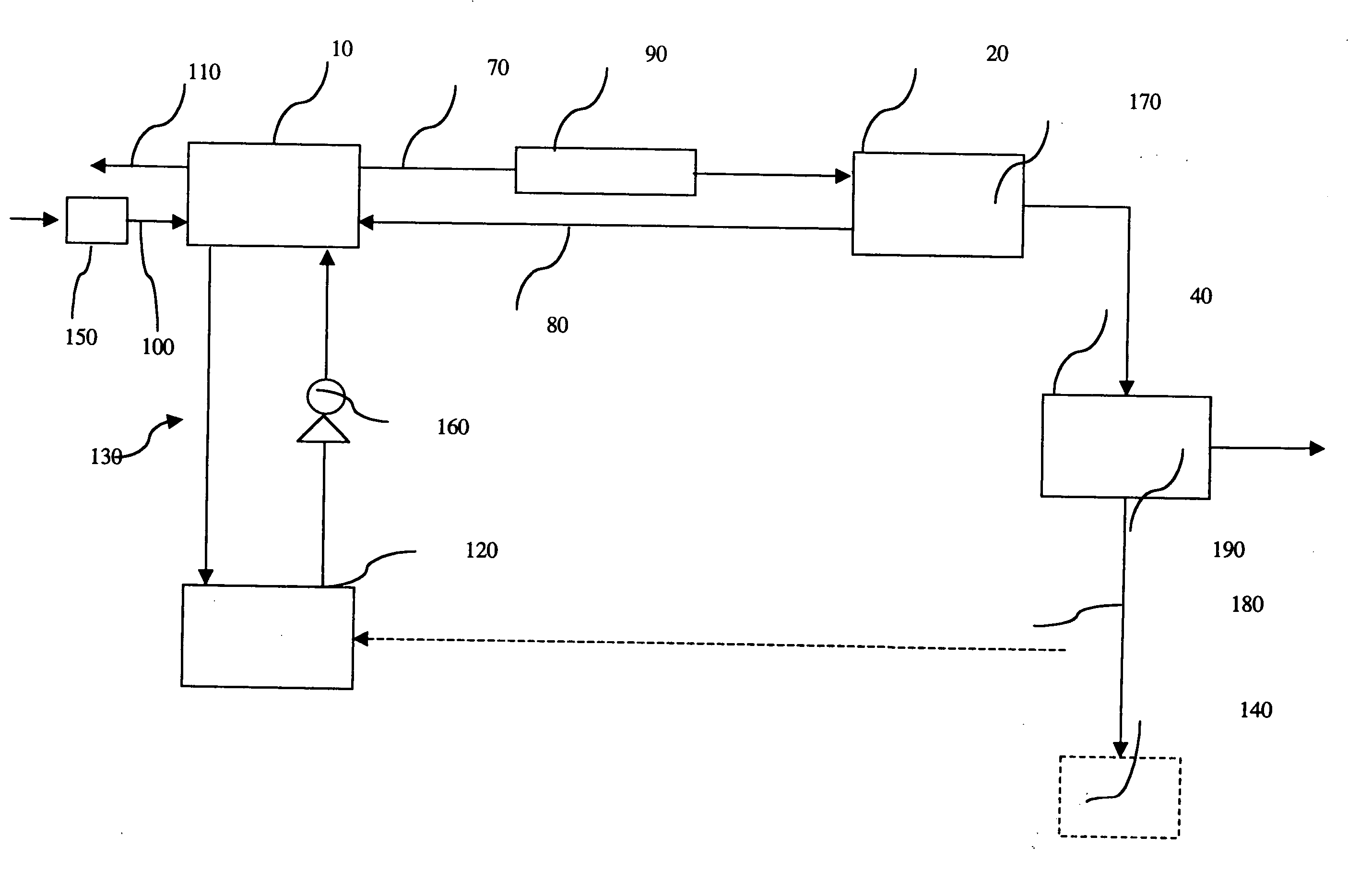
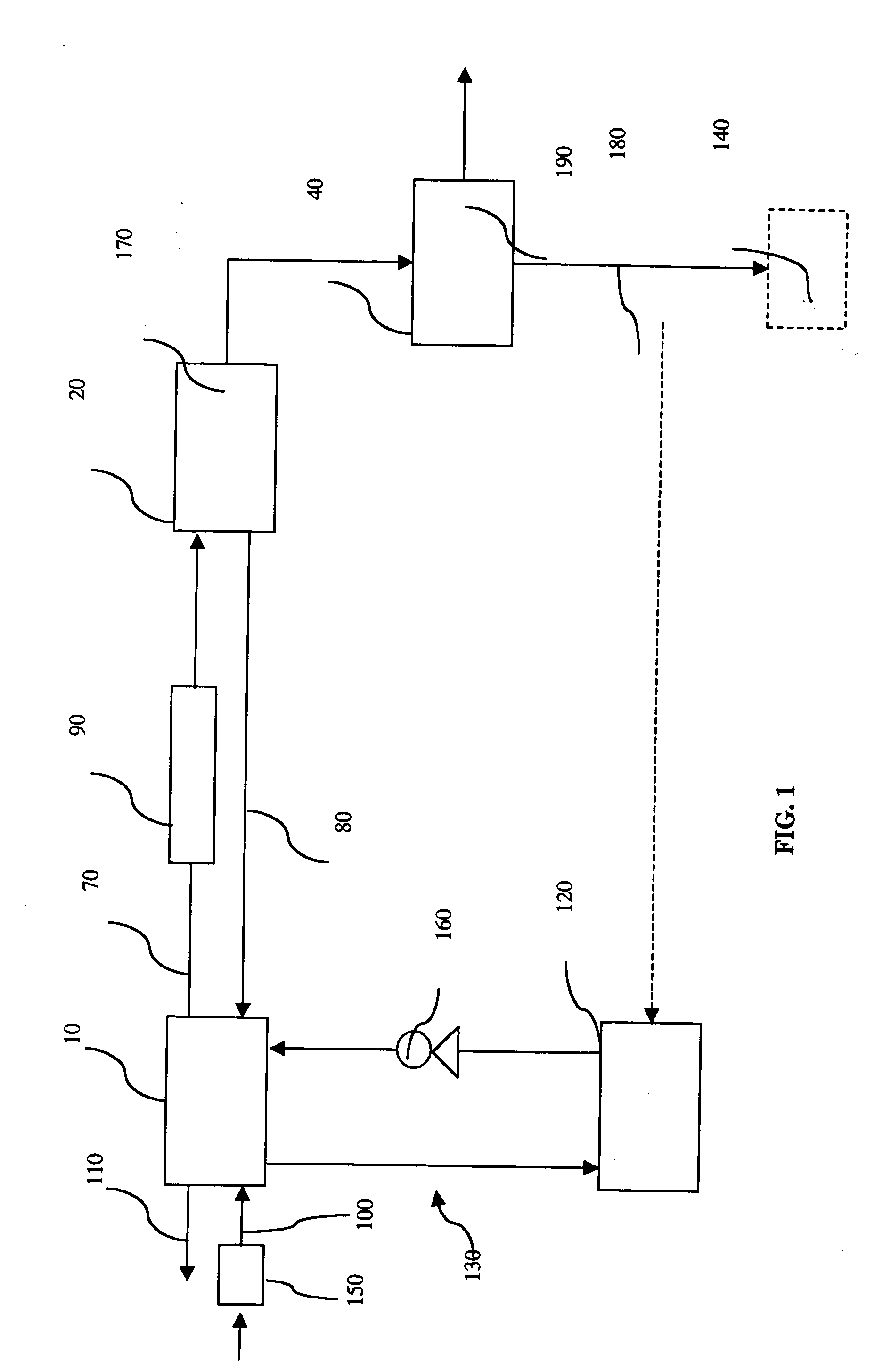
[0046] Referring to FIG. 1, the hydrogen production and water recovery system according to the present invention is shown schematically. The system is connected to one or more fuel cells preferably arranged in a fuel cell stack 10. In a known manner, the fuel cell stack will usually comprise a plurality of fuel cells, but it will be understood that it could comprise just a single fuel cell. For simplicity, reference is made, in the description and claims to a “fuel cell”, and it is to be understood that this encompasses a stack of fuel cells. The water recovery system includes a hydrogen supply vessel, such as a storage tank 20 and a liquid-gas separator 40. The storage tank 20 includes a suitable storage medium, such as a metal alloy capable of storing hydrogen by forming a metal hydride. The alloy forming the metal hydride in the storage tank 20 may be an iron-titanium alloy, mischmetal-nickel alloy, or any other metal alloy that is capable of absorbing hydrogen. An example of a s...

second embodiment

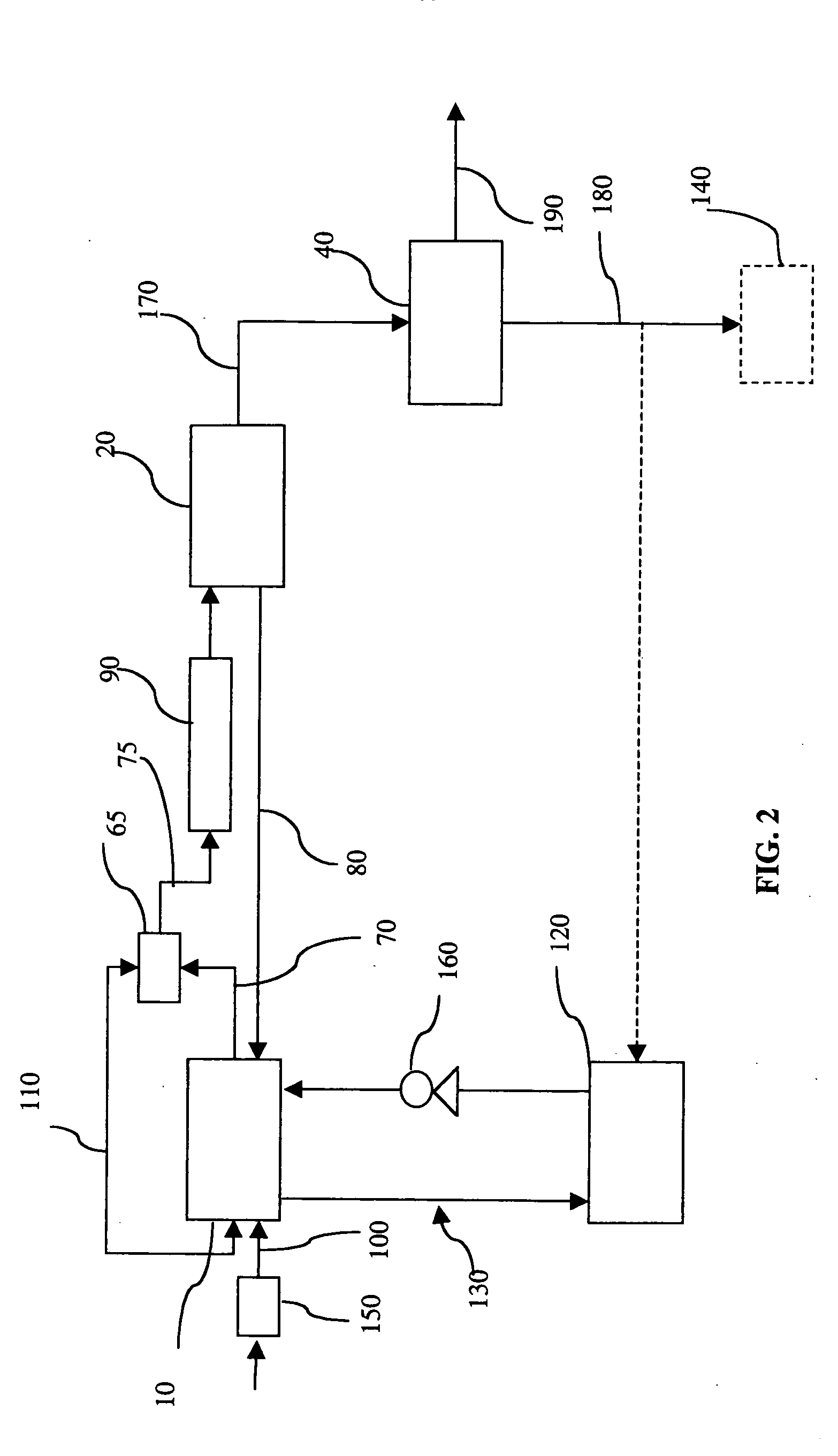
[0064] As described in detail for the second embodiment shown in FIG. 2, the mixture of water and exhaust gases, as process exhaust, flows along the process exhaust passage 75 into heat exchange relationship with the metal hydride or other storage medium storage tank 20. Water is then condensed out of the mixture while heat is transferred to the metal hydride contained in the storage tank 20. The process exhaust stream is then directed to the first liquid-gas separator 40 in which substantially pure liquid water is separated from the gas. The separated gas is then exhausted to the environment through the discharge line 190. The recovered water is then directed to the electrolyzer 30 through the water return line 180 by means of a return pump 50. In the electrolyzer 30, water is electrolyzed according to the following equations:

Anode: H2O→½O2+2H++2e−  (5)

Cathode: 2H++2e−→H2  (6)

[0065] The product of the electrolysis reaction is hydrogen and oxygen. The generated hydrogen is then di...

third embodiment

[0071] In the third embodiment, the present invention significantly improves the water neutrality which is a critical factor of regenerative fuel cell systems. This is especially advantageous in remote applications, where refilling the regenerative system with water is difficult. Experiments have shown that without water recovery from the fuel cell stack 10, each 30 KWh cycle needs a refill of about 15 liters of water for the electrolyzer 30 to recharge the metal hydride storage tank 20 with same amount of hydrogen (20 m3 STP) consumed by the fuel cell stack 10. The present invention reduces this amount by at least 11 liters.

[0072] The operation of the regenerative system according to the embodiment illustrated in FIG. 3 preferably alternates between two modes. The system operates in a fuel cell mode to produce power. In this mode, the water recovered from the exhaust stream as described above is stored in the first liquid gas separator 40. When hydrogen regeneration is required, th...


PUM

PropertyMeasurementUnit
pressureaaaaaaaaaa
pressuresaaaaaaaaaa
pressuresaaaaaaaaaa

Abstract

A hydrogen production and water recovery system for a fuel cell utilizes hydrogen storage in a metal hydride or the like. An exhaust stream from the fuel cell is passed through the storage media, simultaneously to cool the exhaust stream to promote condensation of water vapor and to heat the media to promote generation of hydrogen. The recovered water can be stored, returned to a coolant loop, and at a later time electrolyzed to generate hydrogen.

Description

FIELD OF THE INVENTION [0001] This invention relates to fuel cell systems. More particularly, this invention relates to a system which uses metal hydride to store hydrogen and which recovers water from the fuel cell exhaust stream. BACKGROUND OF THE INVENTION [0002] Fuel cells are seen as a promising alternative to traditional power generation technologies due to their low emissions, high efficiency and ease of operation. Fuel cells operate to convert chemical energy to electrical energy. Proton exchange membrane (PEM) fuel cells typically include an anode (oxidizing electrode), a cathode (reducing electrode), and a selective electrolytic membrane disposed between the two electrodes. In a catalyzed reaction, a fuel such as hydrogen, is oxidized at the anode to form cations (protons) and electrons. The ion exchange membrane facilitates the migration of protons from the anode to the cathode. The electrons cannot pass through the membrane, and are forced to flow through an external cir...

Claims


Application Information

Patent Timeline
Patent Type & Authority Applications(United States)
IPC IPC(8): H01M8/06H01M8/18
CPCH01M8/065Y02E60/528H01M8/186H01M8/0656Y02E60/50
Inventor RUSTA-SALLEHY, ALIJOOS, NATHANIEL IANFRANK, DAVID
Owner HYDROGENICS CORP
Why Eureka
Try Eureka