Array for crystallizing protein, device for crystallizing protein and method of screening protein crystallization using the same

Inactive Publication Date: 2005-04-07
MITSUBISHI RAYON CO LTD
View PDF3 Cites 14 Cited by
  • Summary
  • Abstract
  • Description
  • Claims
  • Application Information

AI Technical Summary

Benefits of technology

[0013] An object of the present invention is to provide a method of conveniently and highly efficiently crystallizing protein to obtain good crystals,

Problems solved by technology

Thus, that a large quantity of samples are used and a long time is spent in searching for conditions for preparing such crystals, which is a current problem.
That is, existing methods require very complicated procedures and thus have been inefficient, in addition to requiring a large quantity of protein samples.
Although the operation of this method is convenient, protein crystals are unable to be efficiently obtained thereby.
This is because crystals cannot be easily obtained, the quality of the resulting crystals is poor (minute crystals are precipitated), and the active control of crystallization conditions is required.
Such a screening method requires an expensive large-scale system involving high throughput in order to examine a large number of conditions using a more minute

Method used


Image

  • Array for crystallizing protein, device for crystallizing protein and method of screening protein crystallization using the same
  • Array for crystallizing protein, device for crystallizing protein and method of screening protein crystallization using the same
  • Array for crystallizing protein, device for crystallizing protein and method of screening protein crystallization using the same

Examples


example 1

Preparation of Hollow-Fiber-Array

[0167] A porous plate has holes which have a diameter of 0.32 mm, and a center distance of which holes is 0.42 mm. Specifically, 10 lines were provided lengthwise and breadthwise, respectively, that is, 100 holes are arrayed in total. A sheet of the porous plate with a thickness of 0.1 mm was superposed on another sheet of the porous plate. Through each hole of the two sheets of the porous plates, 100 hollow fibers made of polyethylene (with an external diameter of approximately 300 μm, internal diameter of approximately 160 μm, and length of approximately 50 cm) (MITSUBISHI RAYON CO., LTD.) were passed. The distance between the 2 sheets of the porous plates was determined to be 30 cm. The hollow fibers were kept strained and fixed at two positions: a position 10 cm away from and a position 40 cm away from one end of the hollow fibers.

[0168] Next, resin materials were poured between 2 sheets of the porous plates. As the resin, a polyurethane resin ...

example 2

Introduction and Immobilization of Polymer Gel to Hollow-Fiber-Array

[0169] A mixed solution consisting of the following compositions was prepared.

Acrylamide3.7 parts by massMethylene bisacrylamide0.3 parts by mass2,2′-azobis (2-amidinopropane) dihydrochloride0.1 parts by mass

[0170] The mixed solution and the hollow-fiber-array obtained in Example 1 were placed in a desiccator. The non-arrayed end parts (free end parts) of the hollow-fiber-arrays were immersed in the mixed solution, and then the desiccator was reduced to pressure to introduce the mixed solution was introduced into the hollow portions of the hollow fibers. Subsequently, the hollow-fiber-array was transferred to a sealed glass container having an interior saturated with water vapor, followed by a polymerization reaction at 80° C. for 4 hours. Thus, a hollow-fiber-array wherein gelatinized products were immobilized in the hollow portions was obtained. As a result, a hollow-fiber-array holding acrylamide gel inside wa...

example 3

Preparation of Hollow-Fiber-Array Thin Section Containing Gel

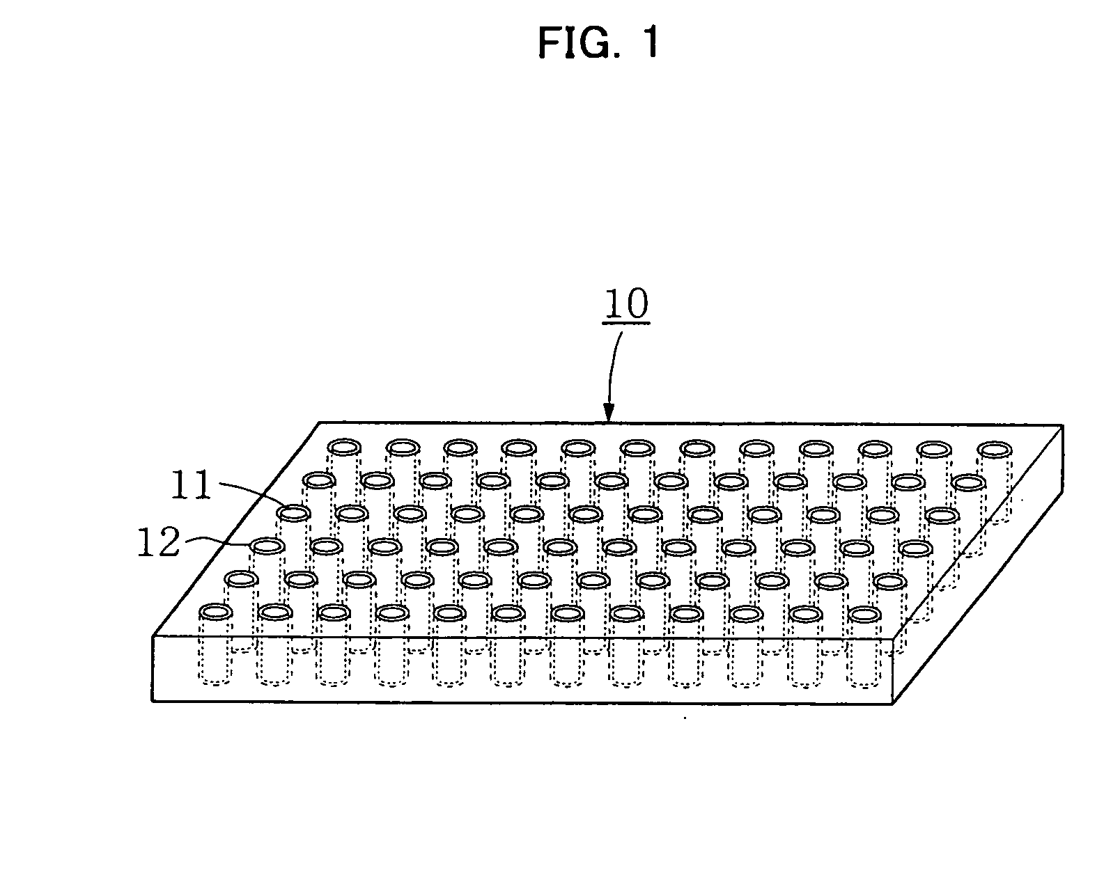
[0171] The hollow-fiber-array containing acrylamide gel obtained in Example 2 was sliced in a direction perpendicular to the fiber axis to have a thickness of approximately 2 mm using a micrtome, thereby obtaining a hollow-fiber-array thin section on which 10-by-10 (length-to-width), that is, 100 bundles in total, of the hollow fibers containing gel were regularly arrayed to form a square (FIG. 1). FIG. 1 shows the hollow-fiber-array thin section containing gel as prepared through Examples 1, 2, and 3. The hollow portions 11 of the hollow fibers 12 were filled with the gel prepared in Example 2.


PUM

PropertyMeasurementUnit
Volumeaaaaaaaaaa
Areaaaaaaaaaaa
Temperatureaaaaaaaaaa

Abstract

The present invention relates to a method of precipitating protein crystals from a protein-containing sample. The present invention also relates to a novel microarray and a novel device for screening for protein crystallization condition. Furthermore, the present invention relates to a method of conveniently and quickly screening for protein crystallization conditions using the microarray or the device having highly integrated and held crystallization conditions even with an extremely small quantity of a sample.

Description

TECHNICAL FIELD [0001] The present invention relates to a method of precipitating protein crystals from a protein-containing sample. The present invention relates to a novel microarray and a novel device for screening for protein crystallization condition. Furthermore, the present invention relates to a method of conveniently and quickly screening for protein crystallization conditions from an extremely small quantity of a sample using the microarray or the device having highly integrated crystallization conditions. BACKGROUND ART [0002] In recent years, the so-called structural genome science movement has been expanding. This involves the exhaustive analysis of protein structure, based on which mechanisms of living phenomena are investigated. In the field of the structural genome science, further labor saving and increased speed are required for the process of structural analysis. To meet these needs, the development of a method of screening for crystallization conditions quickly a...

Claims


Application Information

Patent Timeline
IPC IPC(8): B01J19/00B01L3/00B01L3/06C07B61/00C07K1/30C30B7/00C30B29/58C40B40/18C40B60/14G01N25/14
CPCB01J19/0046G01N25/147B01J2219/00522B01J2219/00585B01J2219/00639B01J2219/00644B01J2219/00673B01J2219/0072B01J2219/00725B01J2219/00745B01J2219/00756B01L3/06B01L3/5085B01L3/50853B01L2300/069B01L2300/0819B01L2300/0822C07B2200/11C07K1/306C30B7/00C30B29/58C40B40/18C40B60/14B01J2219/00317
Inventor TANAKA, ISAOWATANABE, NOBUHISATAKEUCHI, HIROSHIAKITA, TAKASHINAGATA, YUICHIROUSUMI, TOSHINORINISHIJIMA, CHIHARU
Owner MITSUBISHI RAYON CO LTD
Why Eureka
Try Eureka