Automated water treatment system and method of use

a technology of automatic water treatment and automatic discharge, applied in the direction of filtration separation, moving filter element filter, separation process, etc., can solve the problems of large area required for long time that water needs to remain in flocculation tanks and sedimentation basins, and high water purity for many applications

Active Publication Date: 2005-04-14
HYDRO INTERNATIONAL AG +1
View PDF16 Cites 36 Cited by
  • Summary
  • Abstract
  • Description
  • Claims
  • Application Information

AI Technical Summary

Benefits of technology

[0022] Efficient operation in the present filter system is achieved by providing controls that accurately deliver the amount of air introduced into the air lift linked to an influent head pressure gauge that continually monitors the head pressure. This linkage allows the movement of the sand bed to be increased or decreased relative to the size and capability of the solids inventory. When the head pressure begins to increase it is an indication that the solids inventory has begun to exceed the critical mass required to provide proper filtration results and a decrease in head pressure is an indication that the critical mass is below what is required.
[0025] Another benefit of the present invention is that a single filter tower system is able to provide filtering and scrubbing performance equivalent to and better than common dual tower systems.

Problems solved by technology

One of the disadvantages of conventional chemical purification processes is the large area required for the flocculation tanks and sedimentation basins.
A further disadvantage of conventional chemical purification techniques is the long duration that the water needs to remain in the flocculation tank as well as the sedimentation basin.
The use of flocculation tanks and sedimentation basins alone in the chemical purification process does not typically result in a high enough water purity for many applications.
While membrane filtration with a suitably tight membrane can be used to attain a higher level of purification, such membrane filters are expensive and have other disadvantages.
Most of the suspended solids in the feed will be separated near the feed level, which results in the dirtiest sand being in the lower part of the filter.
However, the amount of reject from those filters and the amount of impurities in the reject makes it difficult and costly to dispose of the reject.
However, a system of the type disclosed in U.S. Pat. No. 5,843,308 does not actually provide a solution to the operation of sand filters in series, but instead creates a new and possibly more serious problem.
As a result, the reject from each sand filter has a high level of pollutants and in fact, the pollutants are in a significant concentration level within the reject.
In view of the fact that flocculent fragments are difficult to separate from the reject without renewed precipitation and / or flocculation, the internal recirculation of the reject from the second sand filter that contains such pollutants to the input of the first sand filter results in the concentrated pollutants being returned to the first sand filter.
This increases, rather than decreases, the chances that the pollutants will be in the treated water as it exits the second sand filter.
However, that type of coagulant reacts so quickly that flocculation is essentially immediate.
In general, a system like the one disclosed in U.S. Pat. No. 5,843,308 wherein pollutants are separated by a two-step separation device and the pollutants separated in the second step are returned to the first step increases the risk for build-up and breakthrough of pollutants under real life operating conditions.
In such filters control is generally limited to pacing the injection of polymer and chemicals in the inflows, and monitoring inflow and product flow rates.
However, the prior art does not include improved methods of supervising and controlling such filter systems other than by manual observation and adjustment.

Method used


Image

  • Automated water treatment system and method of use
  • Automated water treatment system and method of use

Examples


Embodiment Construction

[0028] The above described drawing figures illustrate the invention in at least one of its preferred embodiments, which is further defined in detail in the following description. Those having ordinary skill in the art may be able to make alterations and modifications in the present invention without departing from its spirit and scope. Therefore, it must be understood that the illustrated embodiments have been set forth only for the purposes of example and that they should not be taken as limiting the invention as defined in the following.

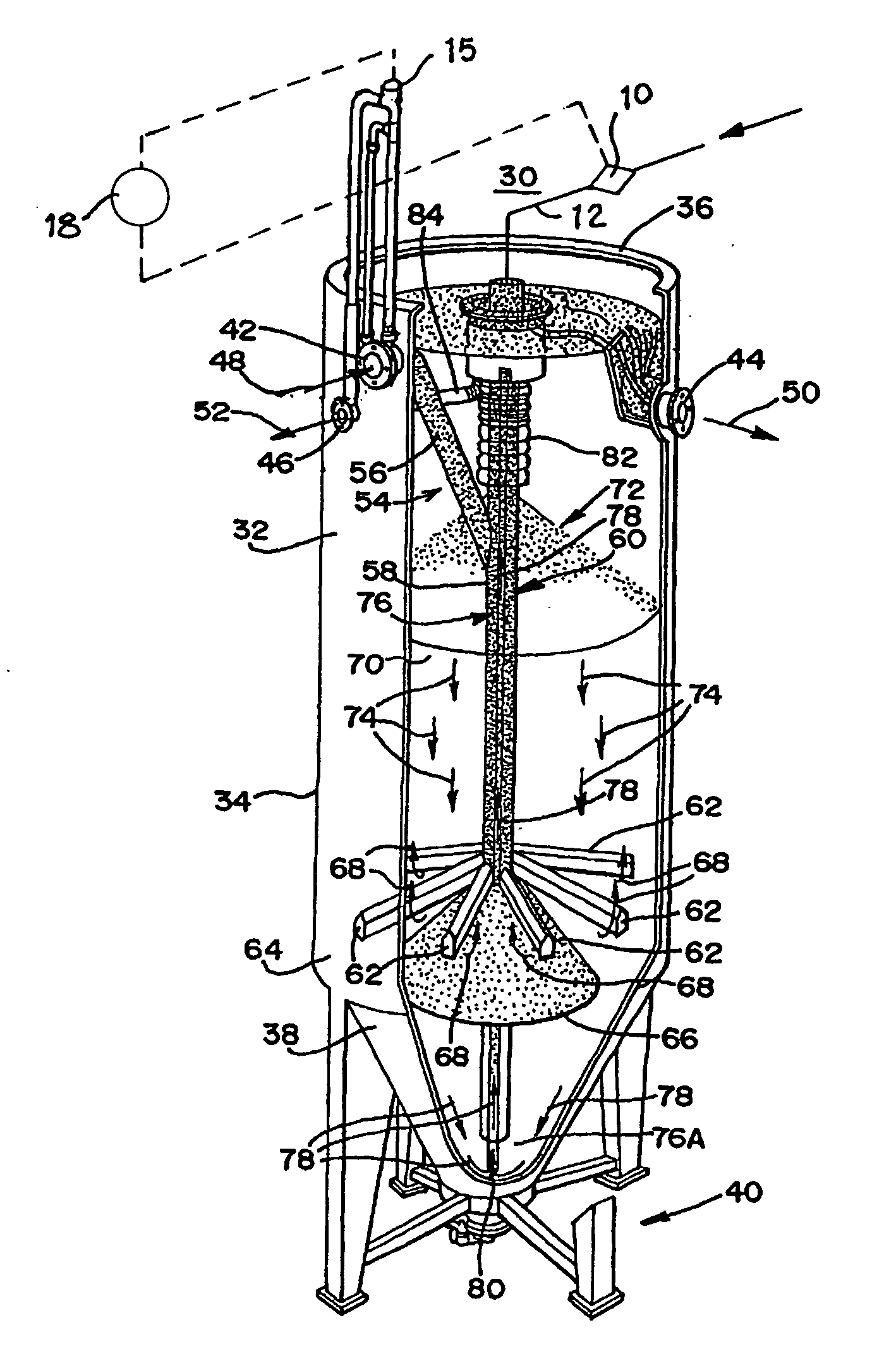
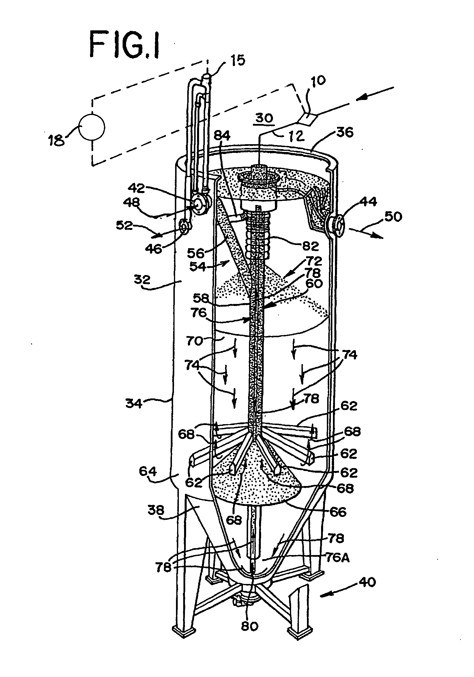
[0029] In the present invention, illustrated in FIG. 1, the sand filter 30 includes an outer housing or tank 32 having an outer, generally cylindrically shaped wall 34 extending from a top end 36 to a funnel-shaped bottom portion 38. The tank 32 is supported by a stand assembly 40 so that the tank 32 can be disposed in a vertical orientation with the stand assembly 40 extending downward from the outer wall 34 and around the funnel-shaped bottom po...


PUM

PropertyMeasurementUnit
pressureaaaaaaaaaa
sizeaaaaaaaaaa
turbidityaaaaaaaaaa

Abstract

An automated method for controlling a solids inventory in a continuous backwashing upflow sand filter system treating a liquid inflow having impurities therein, includes the steps of: monitoring an influent inflow pressure and controlling the air pressure in an air lift pump to maintain a target ratio range between the size of a solids inventory of the system and the size of the sand bed of the system.

Description

BACKGROUND OF THE INVENTION INCORPORATION BY REFERENCE [0001] Applicant(s) hereby incorporate herein by reference, any and all U.S. patents, U.S. patent applications, and other documents and printed matter cited or referred to in this application. FIELD OF THE INVENTION [0002] The present invention relates to the treatment of water and wastewater, and more particularly, to a new and improved method and apparatus for controlling the removal of impurities and pollutants from water and wastewater by controlling each of the process' variables independently in a two-stage continuously operated granular media filtration system. BACKGROUND OF THE INVENTION [0003] In connection with municipal and many industrial water treatment systems, the water or wastewater (referred to herein simply as “water”) needs to be purified. For example, one such system may be a drinking water system where drinking water is produced from surface water and another system may be a municipal wastewater treatment wh...

Claims


Application Information

Patent Timeline
Patent Type & Authority Applications(United States)
IPC IPC(8): B01D24/30
CPCB01D24/30B01D24/4689
Inventor STEDMAN, KEN M.
Owner HYDRO INTERNATIONAL AG
Why Eureka
Try Eureka