Actively controlled harmonic force generator

a harmonic force generator and active control technology, applied in the direction of mechanical vibration separation, dynamo-electric converter control, shock absorbers, etc., can solve the problem that the design and operation of such devices becomes more difficult, and achieve the effect of favorable ratio

Inactive Publication Date: 2005-04-14
UNIV OF CONNECTICUT
View PDF8 Cites 32 Cited by
  • Summary
  • Abstract
  • Description
  • Claims
  • Application Information

AI Technical Summary

Benefits of technology

A novel harmonic force generator and associated control system are disclosed herein to achieve the desired objects with a very favorable ratio between the peak force and device weight. The variation in the force amplitude may be taken from zero to Fmax, while the frequency range varies about ±10% around the nominal operating frequency. Indefinite variations of relative phase angle (i.e., zero to 2π) with respect to a given harmonic signal can be achie...

Problems solved by technology

If one wishes to vary three descriptors, the amplitude, frequency and the phase angle...

Method used


Image

  • Actively controlled harmonic force generator
  • Actively controlled harmonic force generator
  • Actively controlled harmonic force generator

Examples


Embodiment Construction

)

For purposes of the present disclosure, the following nomenclature is used:

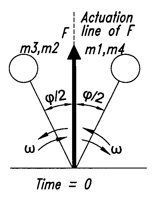
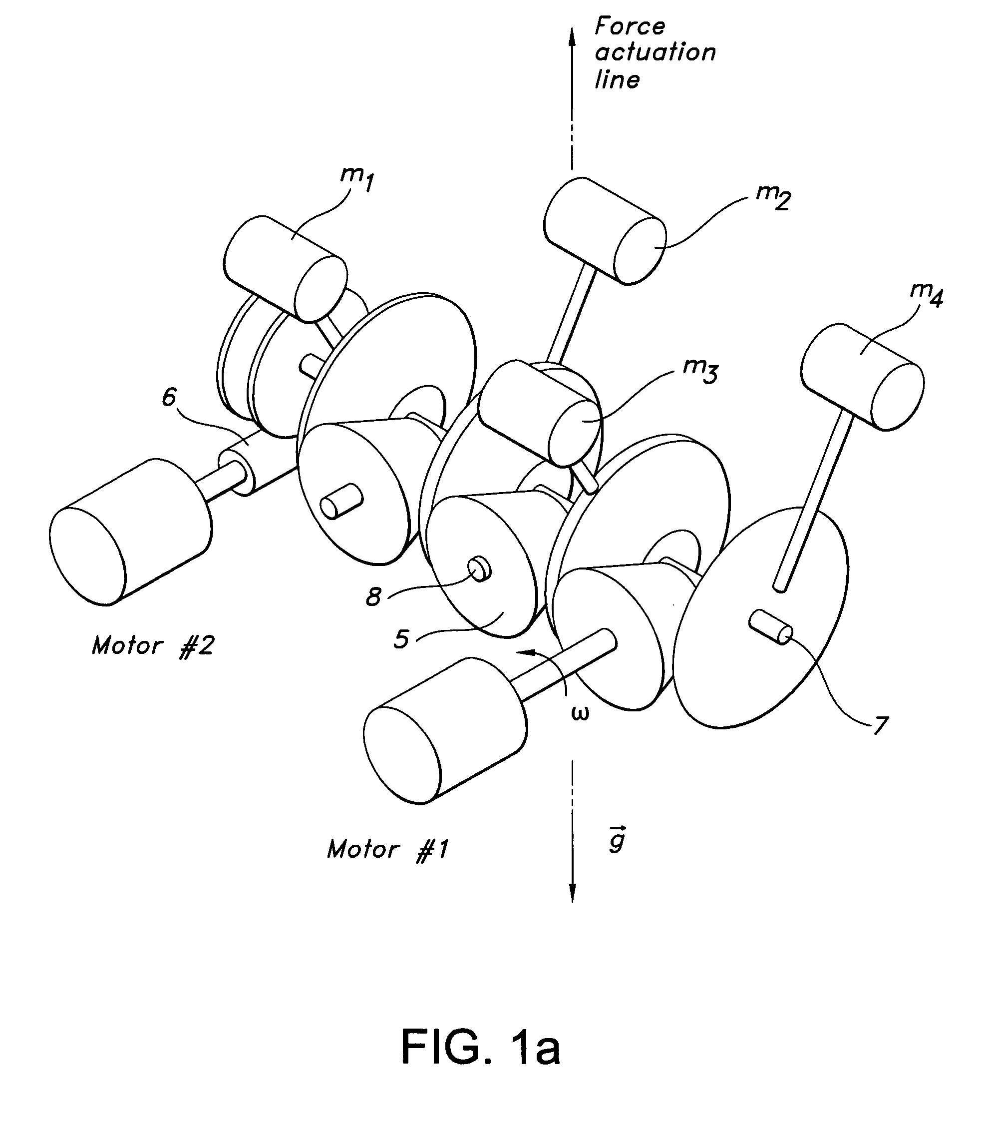
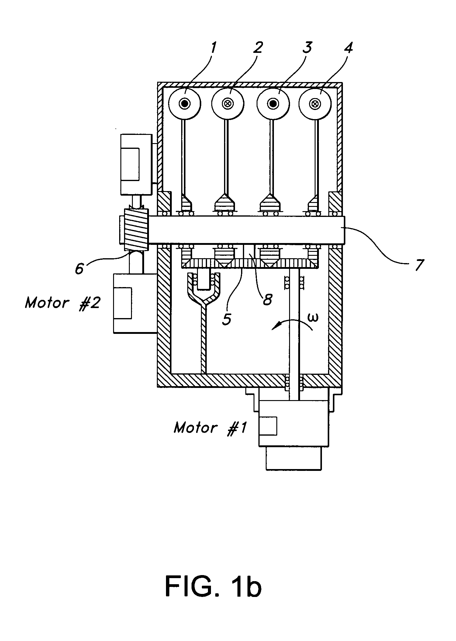
aicoefficients of the polynomial for ω trajectorybicoefficients of the polynomial for φ trajectoryFtotal force in the direction of the actuation lineF13force generated by mass 1 and mass 3 in the directionof the actuation lineF24force generated by mass 2 and mass 4 in the directionof the actuation lineFpeakforce amplitude{right arrow over (F)}force vector{right arrow over (F)}totaltotal force vectorJthe objective functiong, {right arrow over (g)}the gravity constant and the gravity field vectormweight of the single proof massP1, P2power for motor # 1 and #2{right arrow over (r)}local vectorTtransition timeTgtorque caused by gravity force on the main shaftT1, T2control torque of motor # 1 and #2αthe angular position of the single massηthe force / weight ratioφrelative angular position (RAP) between masses m1,m3 and m2, m4φi, φfinitial and final values of relative angular position (RAP)λ1, λ2weight constant...


PUM


Abstract

A “harmonic force generator” (HFG) is provided which creates counter-acting forces to a harmonic excitation. The advantageous HFG devices of the present disclosure may be used in canceling the undesired vibrations on a structure under the influence of a harmonic excitation. There are critical aspects to be controlled in the output force: the amplitude, the frequency and the relative phase with respect to given harmonic signal. All three of these components are adjusted by a closed loop control structure according to the present disclosure. The controller determines the transition time of all three features. The disclosed HFG advantageously produces this harmonically varying force only along a determined axis, with no force component in transverse direction.

Description

TECHNICAL FIELD The present disclosure is directed to force generators that are adapted for harmonic operation and that permit advantageous control of amplitude, frequency and phase angle. BACKGROUND OF THE DISCLOSURE Electromagnetic shakers (also known as voice coil actuators) are commonly utilized for computer controlled force applications. When the force trace becomes harmonic, the devices which use rotating eccentric masses are more feasible to operate. If one wishes to vary three descriptors, the amplitude, frequency and the phase angle of these harmonics, the design and the operation of such devices becomes more challenging. The technical literature provides background information concerning prior development efforts directed to counteracting vibrational forces associated with harmonic excitation of structures, especially in the rotorcraft industry. The following publications generally fall within the technical field of the present disclosure: Chopra, I., “Status of Applic...

Claims


Application Information

Patent Timeline
IPC IPC(8): B06B1/16F16F7/10H02K7/06H02P1/54H02P23/04
CPCB06B1/166H02P23/04H02K7/06F16F7/1005
Inventor OLGAC, NEJATMIKUS, OLDRICHSIPAHI, RIFAT
Owner UNIV OF CONNECTICUT
Why Eureka
Try Eureka