Integrated arrangement of optical fibers in a conductor

a technology of optical fibers and conductors, applied in the field of electrical conductors, can solve the problems of inability to conduct an electrical signal reasonably, damage to the electrical conductor itself or to other components adjacent to the conductor, and inability to use metallic sensors at mass locations, etc., and achieve the effect of low manufacturing cos

Inactive Publication Date: 2005-04-21
ALSTOM TECH LTD
View PDF9 Cites 11 Cited by
  • Summary
  • Abstract
  • Description
  • Claims
  • Application Information

AI Technical Summary

Benefits of technology

[0009] One of the numerous aspects of present invention is to make available an electrical conductor, particularly a bar suitable for use in a generator or transformer, into which with comparatively low manufacturing cost an optical measuring device can be integrated. In particular, a freely selectable arrangement is to be possible of the optical measuring device at different positions of the conductor, so that the quantiti

Problems solved by technology

If the temperature exceeds a certain maximum value, damage to the electrical conductor itself or also to other components adjacent to the conductor can occur.
In electrical machines, due to the often very high current fluxes and the strong electromagnetic fields built up as a consequence of these high current fluxes, conduction of an electrical signal is not reasonably possible.
Moreover metallic sensors cannot be used at mass locations which lie at a high electrical potential.
More

Method used


Image

  • Integrated arrangement of optical fibers in a conductor
  • Integrated arrangement of optical fibers in a conductor
  • Integrated arrangement of optical fibers in a conductor

Examples


Embodiment Construction

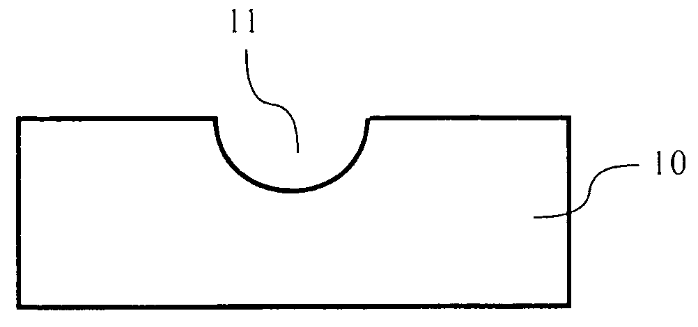
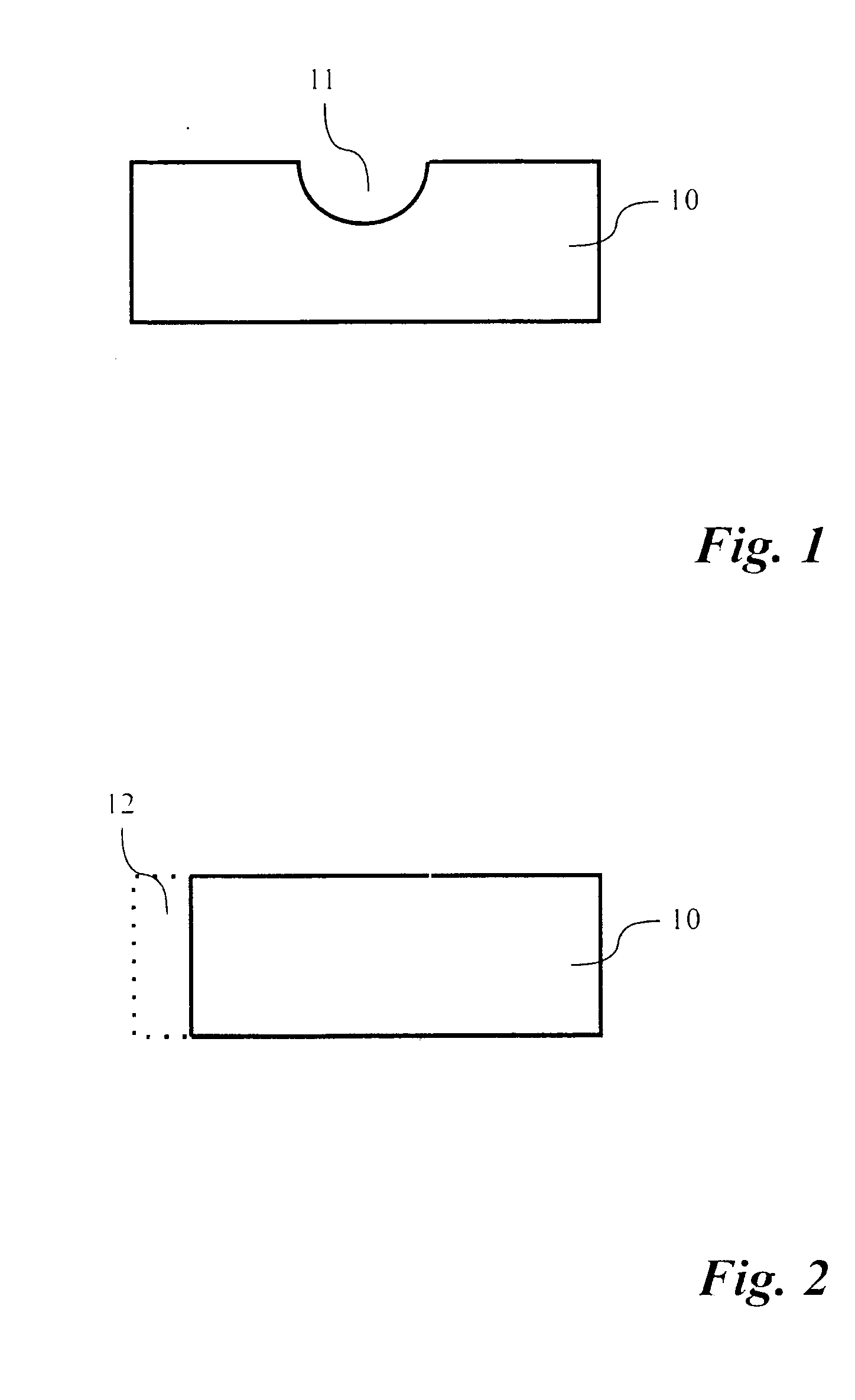
[0037]FIG. 1 is a schematic diagram of a cross section through an electrical conductor 10 embodied according to the principles of the present invention. The conductor shown here is suitable for use in an electrical machine, particularly in a generator or a transformer. The conductor 10 has a substantially rectangular cross section. The extension of the conductor perpendicularly of the plane of the drawing forms the longitudinal direction of the conductor. In order to be able to arrange an optical waveguide integrated into the conductor, the conductor 10 shown in FIG. 1 has on its upper side a slot-shaped groove 11. The groove floor of the groove 11 is made half-round here. It cannot be seen in the diagram here that the slot-shaped groove 11 extends in the longitudinal direction of the groove 11 from one transverse side of the conductor to at least in the middle of the conductor.

[0038] An optical waveguide or another signal conductor can be laid in the slot-shaped groove 11. The sen...


PUM


Abstract

An electrical conductor and in particular a conductor bar of an electrical machine, particularly a generator or transformer, in which an optical measuring device can be integrally arranged. A measuring unit includes an electrical conductor and an optical measuring device arranged in the conductor, and a production method for producing such an electrical conductor is described. The electrical conductor (10), having a conductor cross section and also an extent in the conductor longitudinal direction, includes a recess (11, 12, 13) in the conductor longitudinal direction at least along a section of the conductor, for integrated arrangement of a signal conductor, in particular an optical waveguide.

Description

[0001] This application claims priority under 35 U.S.C. § 119 to German application number 103 31 486.5, filed Jul. 11, 2003, the entirety of which is incorporated by reference herein. BACKGROUND [0002] 1. Field of the Invention [0003] The invention relates to an electrical conductor and particularly a conductor bar, or a partial conductor of a conductor bar, which can in particular be used in a generator or transformer, and into which conductor bar, or the partial conductor of a conductor bar, an optical measuring device can be integrated. Furthermore the invention relates to an optical measuring unit including an electrical conductor and an optical measuring device arranged in the conductor, and also to a method of producing such an electrical conductor. [0004] 2. Brief Description of the Related Art [0005] In electrical generators, transformers, and also other electrical machines, conductors, so-called conductor bars (bars for short) are used for conducting the electrical current...

Claims


Application Information

Patent Timeline
IPC IPC(8): G01K1/14G01K11/32H01F27/28H01F27/40H02K3/04H02K3/14H02K11/00
CPCG01K1/14G01K11/32H01F27/28H02K11/0047H02K3/04H02K3/14H02K11/001H01F2027/406H02K11/20H02K11/25
Inventor DRUBEL, OLIVERIZQUIERDO, ALBERTOSCHERF, GUNTER
Owner ALSTOM TECH LTD
Why Eureka
Try Eureka