Voltage controlled variable capacitor

a voltage control and capacitor technology, applied in the field of voltage control variable capacitors, can solve the problems of poor linearity of the change of the capacitance value with respect to the change of the control voltage, the difficulty of the varactor in controlling, and the inability of the voltage control varactor to make so high the sensitivity of the change of the capacitance value with respect, etc., to achieve the effect of easy control of the capacitance value, good linearity and high precision

Inactive Publication Date: 2005-04-21
COLLABO INNOVATIONS INC
View PDF2 Cites 16 Cited by
  • Summary
  • Abstract
  • Description
  • Claims
  • Application Information

AI Technical Summary

Benefits of technology

[0015] The present invention was made in view of the aforesaid circumstances and an object of the invention is to provide a voltage controlled variable capacitor which can change a capacitance value thereof in a wide controlled voltage range and control the capacitance value easily with a high precision without complicating the circuit configuration thereof. Further, an object of the invention is to provide a voltage controlled variable capacitor which can change a capacitance value thereof with a good linearity.

Problems solved by technology

However, in general, such the voltage controlled varactor can not make so high the sensitivity of the change of the capacitance value with respect to the change of the control voltage.
Further, the linearity of the change of the capacitance value with respect to the change of the control voltage is not good.
Thus, the voltage controlled varactor has difficulty in its control and hence has difficulty in using for compensating the frequency of the crystal oscillator.
Thus, the circuit configuration becomes complicated and it is difficult to control the capacitance value with a high precision.
Further, since the circuit configuration becomes complicated, it is difficult to reduce the circuit scale thereby to reduce a chip area.

Method used


Image

  • Voltage controlled variable capacitor
  • Voltage controlled variable capacitor
  • Voltage controlled variable capacitor

Examples


first embodiment

(First Embodiment)

[0046] In first and second embodiments, the explanation will be made as to a case where the gate lengths of MOS transistors are respectively differentiated among a plurality of variable capacitance means thereby to differentiate threshold voltages among the MOS transistors respectively.

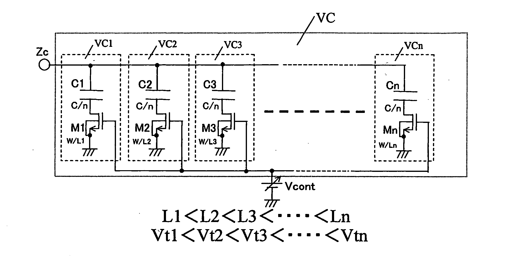
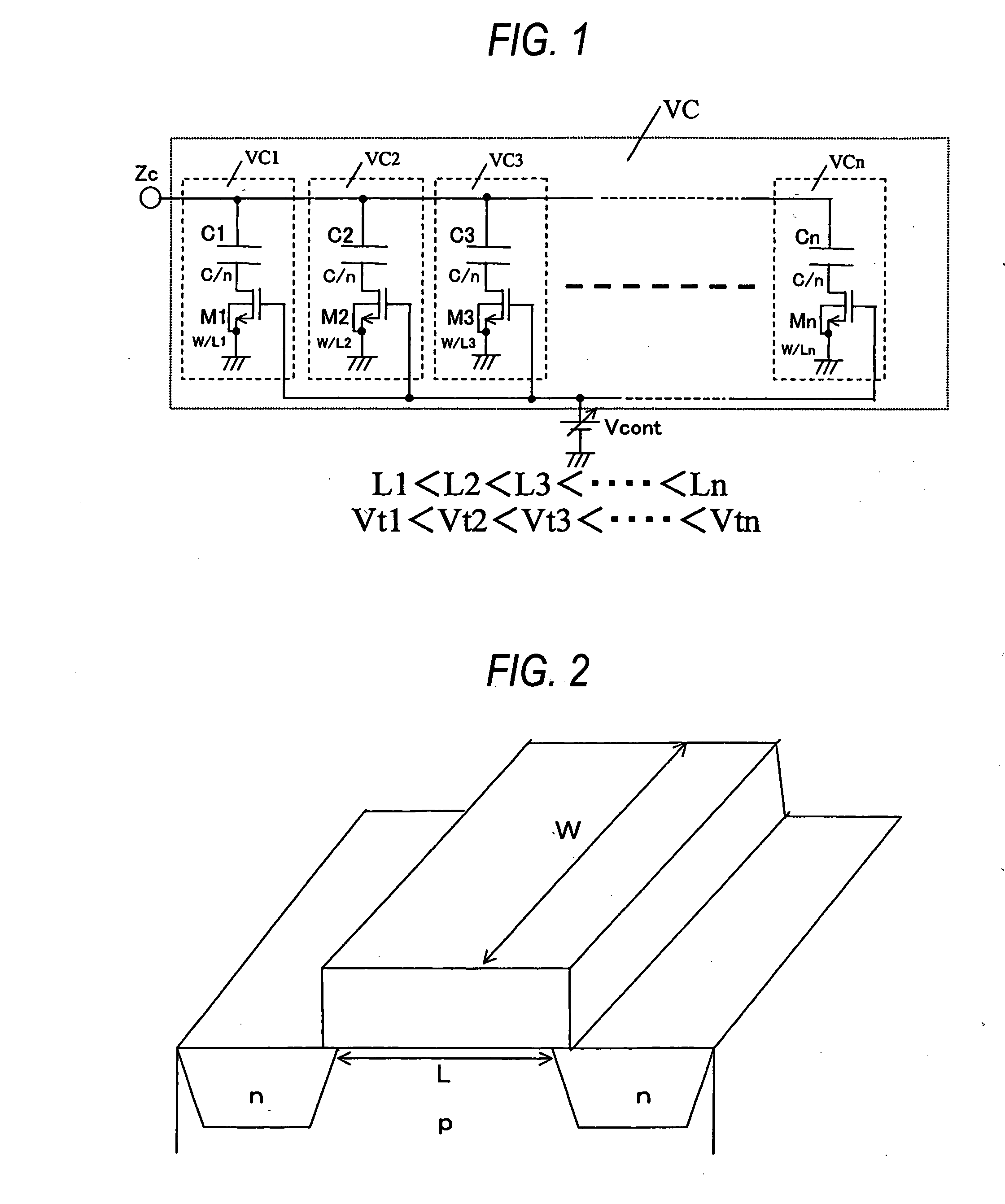
[0047]FIG. 1 is a diagram showing the configuration of a voltage controlled varactor for explaining the first embodiment of the invention. The voltage controlled varactor VC according to the embodiment is configured in a manner that varactors VCk (k=1, 2, - - - , n, where n is an integer equal to or more than 2), each formed by a series connection of a fixed capacitor Ck (k=1, 2, - - - , n, where n is an integer equal to or more than 2) of a capacitance value of C / n and a MOS transistor Mk (k=1, 2, - - - , n, where n is an integer equal to or more than 2) of N channel type, are connected in parallel. In the voltage controlled varactor according to the embodiment, a capacitance value...

second embodiment

(Second Embodiment)

[0056]FIG. 5 is a diagram showing the configuration of the voltage controlled varactor for explaining the second embodiment of the invention. In the figure, portions identical to those of FIG. 1 explained in the first embodiment are referred to by the common symbols.

[0057] In the voltage controlled varactor according to this embodiment, the positional relation between a fixed capacitor Ck (k=1, 2, - - - , n, where n is an integer equal to or more than 2) and a MOS transistor Mk (k=1, 2, - - - , n, where n is an integer equal to or more than 2) in each of varactors VCk (k=1, 2, - - - , n, where n is an integer equal to or more than 2) is reverse to that of the first embodiment. That is, according to this embodiment, the varactor VCk is arranged in a manner that the one end of the fixed capacitor Ck is grounded and the other end thereof is connected to the source of the MOS transistor Mk. The MOS transistor Mk is connected at its drain to a terminal Zc and is suppl...

third embodiment

(Third Embodiment)

[0059] In third and fourth embodiments, the explanation will be made as to a case where the gate widths of MOS transistors are respectively differentiated among a plurality of variable capacitance means.

[0060]FIG. 6 is a diagram showing the configuration of the voltage controlled varactor for explaining the third embodiment of the invention. In this figure, portions identical to those of FIG. 1 explained in the first embodiment are referred to by the common symbols. In the first embodiment, the gate lengths of MOS transistors M1 to Mn are respectively differentiated from one another thereby to differentiate the threshold voltages among the MOS transistors, respectively. In contrast, in this embodiment, the gate widths of the MOS transistors M1 to Mn are set to have different values (W1>W2>W3> - - - >Wn) thereby to differentiate threshold voltages Vtk (Vt1

[0061] The MOS transistors M1 to Mn constituting the...


PUM


Abstract

To provide a voltage controlled variable capacitor which can change a capacitance value thereof in a wide controlled voltage range and control the capacitance value easily with a high precision without complicating the circuit configuration thereof, and to provide a voltage controlled variable capacitor which can change a capacitance value thereof with a good linearity.
The voltage controlled varactor is configured in a manner that varactors VCk, each formed by a series connection of a fixed capacitor Ck (k=1, 2, - - - , n) and a MOS transistor Mk of N channel type, are connected in parallel. The MOS transistors M1 to Mn are configured in a manner that gate widths W are same but gate lengths L1 to Ln are elongated sequentially (that is, L1<L2< - - - <Ln) so that the threshold voltages thereof are differentiated from one another.

Description

BACKGROUND OF THE INVENTION [0001] 1. Field of the Invention [0002] The present invention relates to a voltage controlled variable capacitor which capacitance value is changed in accordance with a control voltage applied thereto. [0003] 2. Description of the Related Art [0004] In signal processing circuits used in communication terminals etc., oscillators oscillating with high precision are desired in order to generate clock signals accurately. Conventionally, in order to improve the oscillation accuracy of a crystal oscillator used in general, there is known a VCXO (voltage controlled crystal oscillator) that includes a voltage controlled variable capacitor (a voltage controlled varactor) which capacitance value changes in accordance with a control voltage and a crystal vibrator which oscillates at a frequency according to the capacitance value of the voltage controlled varactor. There is also known a TCXO (a temperature compensated crystal oscillator or a crystal oscillator with a...

Claims


Application Information

Patent Timeline
Patent Type & Authority Applications(United States)
IPC IPC(8): H01L27/04H01L21/822H01L29/93H01L29/94H03B1/00H03B5/32
CPCH03B5/32H03J2200/10H03B2201/0266
Inventor MATSUURA, JUNICHIKAMINISHI, EIICHIFUJITA, NORIYUKI
Owner COLLABO INNOVATIONS INC
Why Eureka
Try Eureka