Internet interactive realtime video image acquisition system based in low earth orbit

a realtime video and image acquisition technology, applied in the field of space-based remote sensing and internet interactive media content, can solve the problems of reducing resolution, increasing cost and complexity, and the type of system not producing realtime data that can capture dynamic events, so as to reduce failure probability

Inactive Publication Date: 2005-04-21
MURPHY SCOTT DAMIAN
View PDF4 Cites 22 Cited by
  • Summary
  • Abstract
  • Description
  • Claims
  • Application Information

AI Technical Summary

Benefits of technology

[0012] The main objective of the present invention is to provide any user connected to the internet a live and controllable view of the Earth, Earth's near space environment, visible celestial objects, and any objects of interest that are or could be visible from an Earth orbiting vantage point.
[0015] The video image subsystem includes a Charge Coupled Device (CCD) type video image sensor, along with its associated optics, that is integrated to a multi-axis pointing device or mechanism that can physically move the image sensor about any or all three spatial axes. This assembly further includes one or more apparatus', such as integrated shielding, that serve to protect the image assembly from the extreme thermal environment as well as help protect it from space debris impacts and radiation hazards. This integrated video image sensor assembly can include redundant actuators in order to reduce the failure probability. This subsystem also includes the sensor pointing control electronics and image read out electronics as well as any associated interfaces for data handling and electrical power. The image processing electronics and / or software could be integrated either with the subsystem or with satellite bus.

Problems solved by technology

This has been accomplished by the use of digital image sensors (such as Charged Coupled Devices or CCDs) that are increasingly pixelated and are coupled to optics systems of increasing cost and complexity.
As is demonstrated here, while the images are of very high spatial quality, this type of system will not produce realtime data that can capture dynamic events that have time scales of minutes or seconds.
Another problem with trying to obtain these high resolution images is that these sensing instruments require stable backgrounds in order to reduce pixel or image blur which degrades resolution.
This stability requirement along with the high resolution requirement drives the cost and complexity up to points where only governments can afford to build and operate them.
These communications have been typically low rate data and require scheduled up and downlinks that may be hours apart for Low Earth Orbiting satellites.
These links are also built for and used by specialized scientific user communities (typically government or University laboratories) and are not designed to allow for generalized interactivity as described in this patent specification.
However these cameras were fixed and only recorded a predetermined view.
These image capture activities have not generally been available to people outside the immediate space activity related community.
There have been some cameras such as the student camera on the International Space Station that can be operated by students on the ground but this has been a still image camera that does not allow for true interactivity.
However none of the systems bring true real-time (a few seconds delay), interactivity (direct pointing and zoom control of the camera), low cost (development cost and costs to the user), and availability to anyone with an internet connected computer.

Method used


Image

  • Internet interactive realtime video image acquisition system based in low earth orbit
  • Internet interactive realtime video image acquisition system based in low earth orbit
  • Internet interactive realtime video image acquisition system based in low earth orbit

Examples


Embodiment Construction

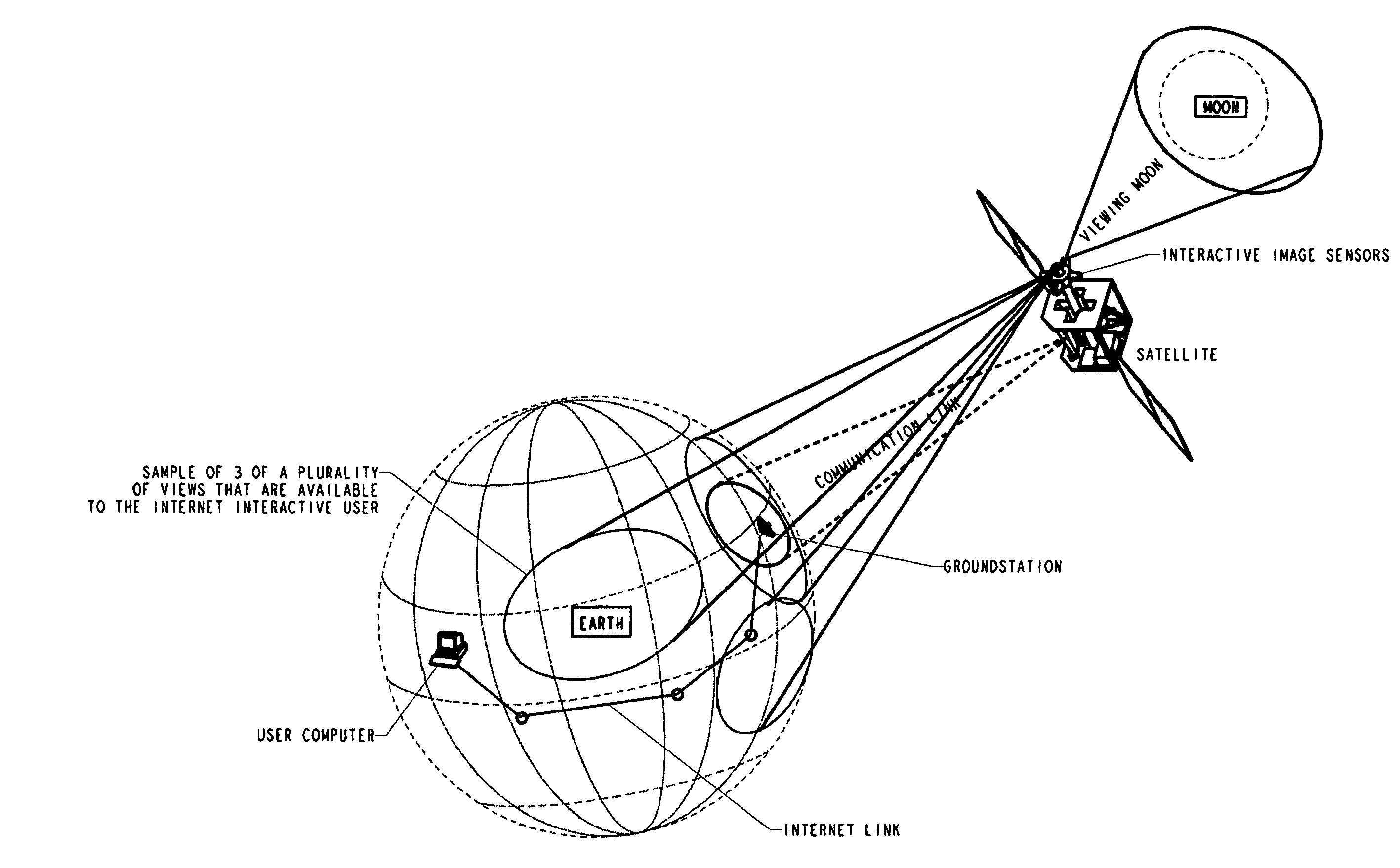
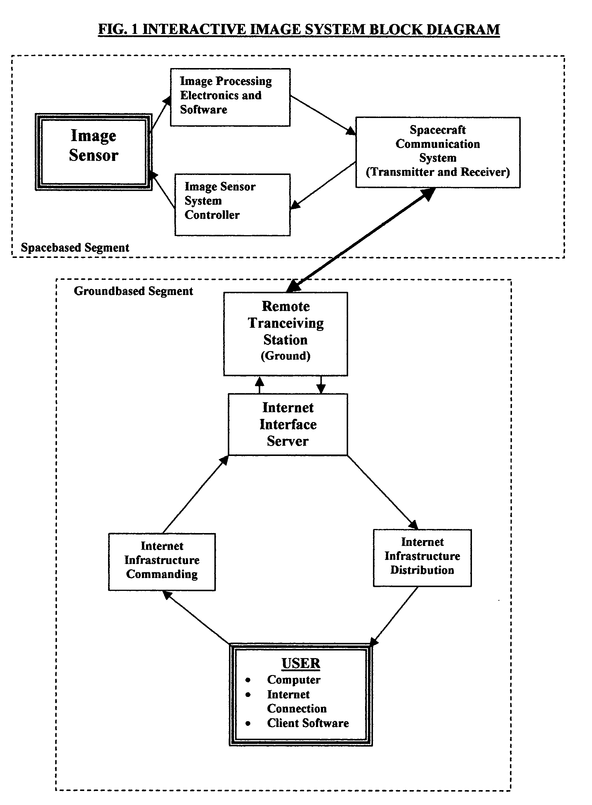
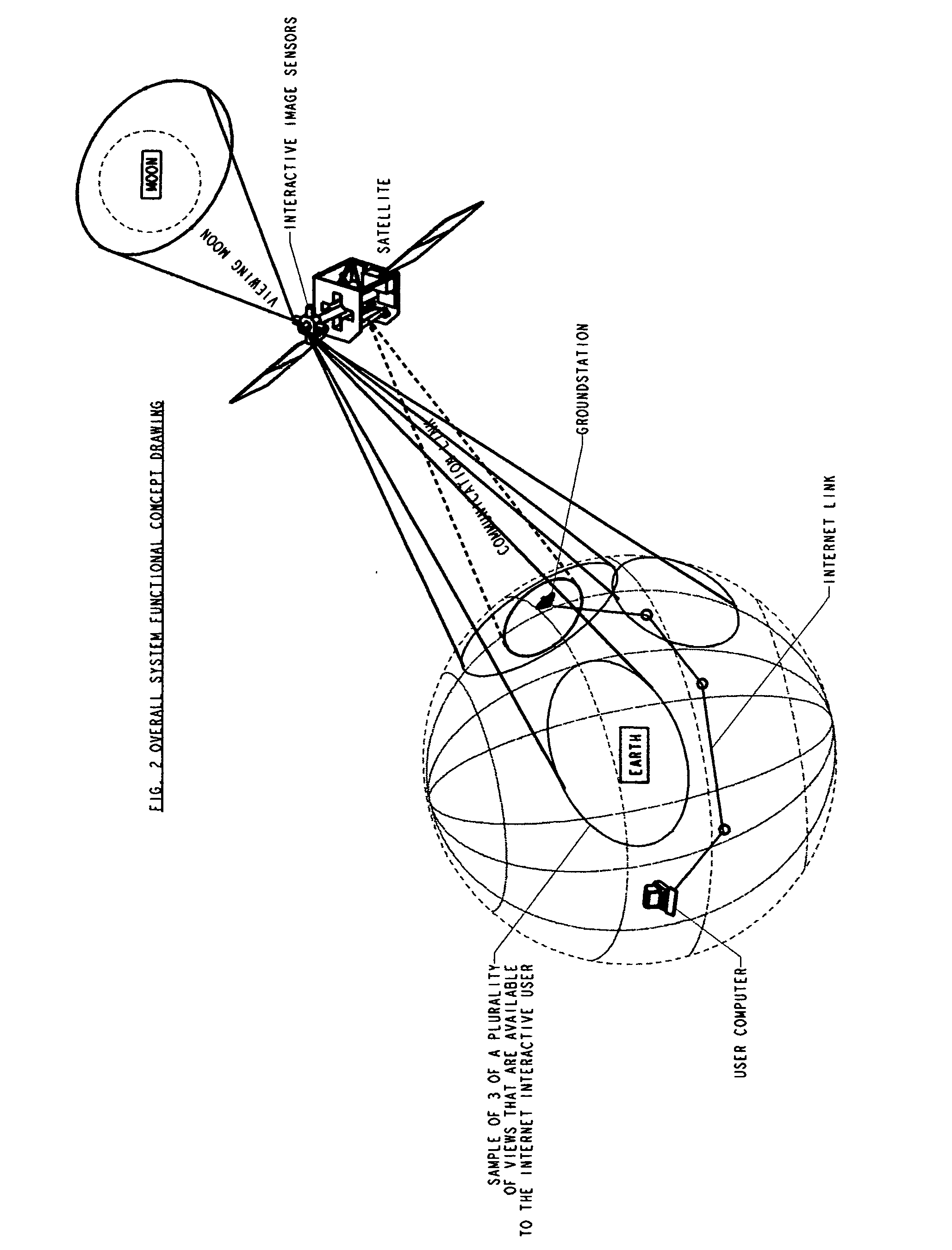
[0024] The present invention is a system that comprises several subsystem components that function together to satisfy the main objective. The components include the video image subsystem, the satellite bus, the remote transceiving station, the internet connection and distribution system, and the client or user interface.

[0025] The satellite bus subsystem provides the physical structure to which the image subsystem is attached as well as electrical power using either batteries or solar panels. The satellite bus also provides other system resources such as data handling and storage with an onboard computer and associated electronics, stationkeeping including 3 axis stability, position and altitude determination through the Global Positioning System (GPS), and nadir pointing capability of the communication antennae. The satellite bus is designed to provide these system resources in support of the video image system. In order to reduce costs and complexity, the satellite is 3 axis sta...


PUM


Abstract

A system, method, and apparatus for obtaining and distributing live and real-time video imagery of the Earth, Earth's local space environment, the Moon, celestial bodies and any events or objects that are visible to a Low Earth Orbiting space based video imaging system that is interactively controlled by any operator using an internet connected computer. A LEO spacecraft serves as the platform for the suite of multiaxis controlled video image sensors. The spacecraft's communication system provides the high data rate downlink (and lower rate uplink) through one or several or multiplexed S- or X-band transceivers. The tranceiver(s) broadcast the video stream down to one or more remote transceiving stations sited around the world. The tranceiving stations are directly connected to the internet and provide live real-time streaming of the downlinked imagery data. The internet connected remote ground stations also provide a real-time interactive control environment (less than 3 seconds for interactive loop) whereby any operator who is authorized can actively control one or more of the onboard video image sensors.

Description

BACKGROUND OF THE INVENTION [0001] The fields of endeavor to which this invention generally pertains to are space based remote sensing and internet interactive media content. The invention described herein seeks to combine these fields via a system, method and apparatus that performs space based remote sensing while being interactively controlled and delivering live video media content through the internet infrastructure. [0002] Space based remote sensing has evolved over the past 30+ years to where it has become common to see and use the imagery generated by satellites for studying weather and the atmosphere, analyzing land regions for agriculture, monitoring the oceans and even surveillance of large scale human activity on Earth. In order to satisfy the requirements of the science and commercial sectors it has been the focus of the remote sensing industry to develop the highest resolution images while working toward decreasing the time between images of the same location or event....

Claims


Application Information

Patent Timeline
Patent Type & Authority Applications(United States)
IPC IPC(8): H04B7/185H04N7/18H04N7/20H04N9/47
CPCH04B7/18595H04N21/2187H04N21/6587H04N21/6175H04N21/6143
Inventor MURPHY, SCOTT DAMIAN
Owner MURPHY SCOTT DAMIAN
Why Eureka
Try Eureka