
Aerosol charge altering device

Inactive Publication Date: 2005-04-21
TSI INC
View PDF8 Cites 38 Cited by
  • Summary
  • Abstract
  • Description
  • Claims
  • Application Information

AI Technical Summary

Benefits of technology

[0027] Due to the short period length, charged aerosol particles can travel only a very short distance during one period, so that the deposition or precipitation of the aerosol is kept very low.
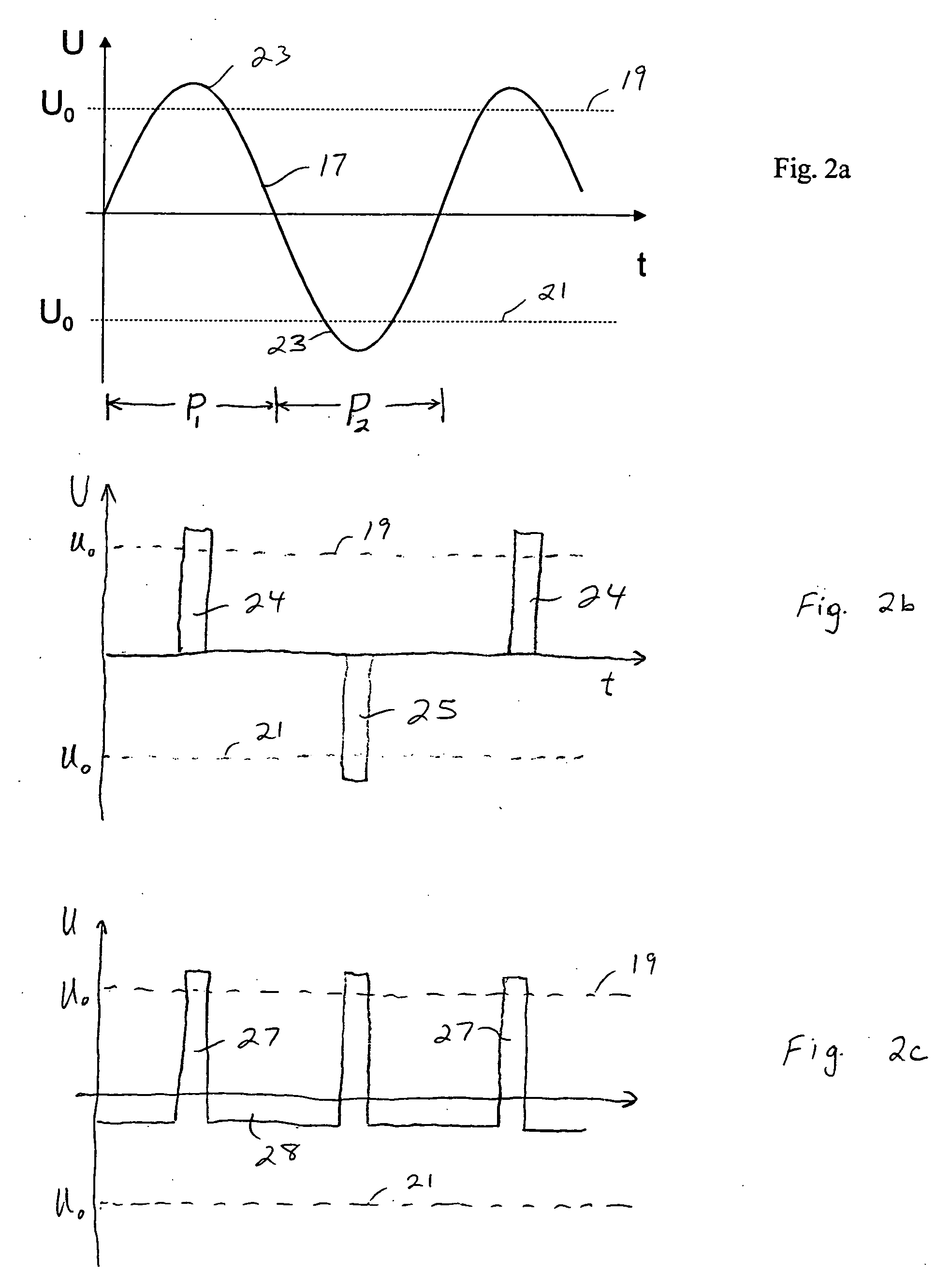
[0059] Preferably, the first and second voltages are produced by an AC voltage source coupled to the conductive structure, i.e. the passive electrode. Generating the AC voltage at a frequency of at least 100 Hz determines a cycle time at most 0.01 seconds. Thus, every second includes one hundred cycles, each including one period or time segment for each polarity and two reversals in the polarity of the electrical field between the active and passive electrodes. The rapid reversals in field polarity substantially eliminate the loss of ions or charged particles through deposition onto the passive electrode. In the context of bipolar charging, the rapid reversals produce a closer approximation to charging with a radioactive source.

Problems solved by technology

To be sure, the application field of radioactive sources is limited by several disadvantages: The safety requirements concerning the radioactive source are high.
The costs are very high.
Previous devices avoided producing the corona discharge in the aerosol space itself, because the electric field needed to produce the corona in the aerosol space causes partial precipitation of the aerosol, and because charging in this field does not produce the desired charge state of bipolar diffusion charging.
This dilutes the aerosol.
In addition, most of the gas ions are deposited onto the walls or are lost through recombination.
However, the methods using discharging in the aerosol space achieve only a charge reduction (Hinds) or charging to an undefined bipolar charge state (Gutsch).
In addition, considerable deposition occurs.

Method used


Image

  • Aerosol charge altering device
  • Aerosol charge altering device
  • Aerosol charge altering device

Examples


Embodiment Construction

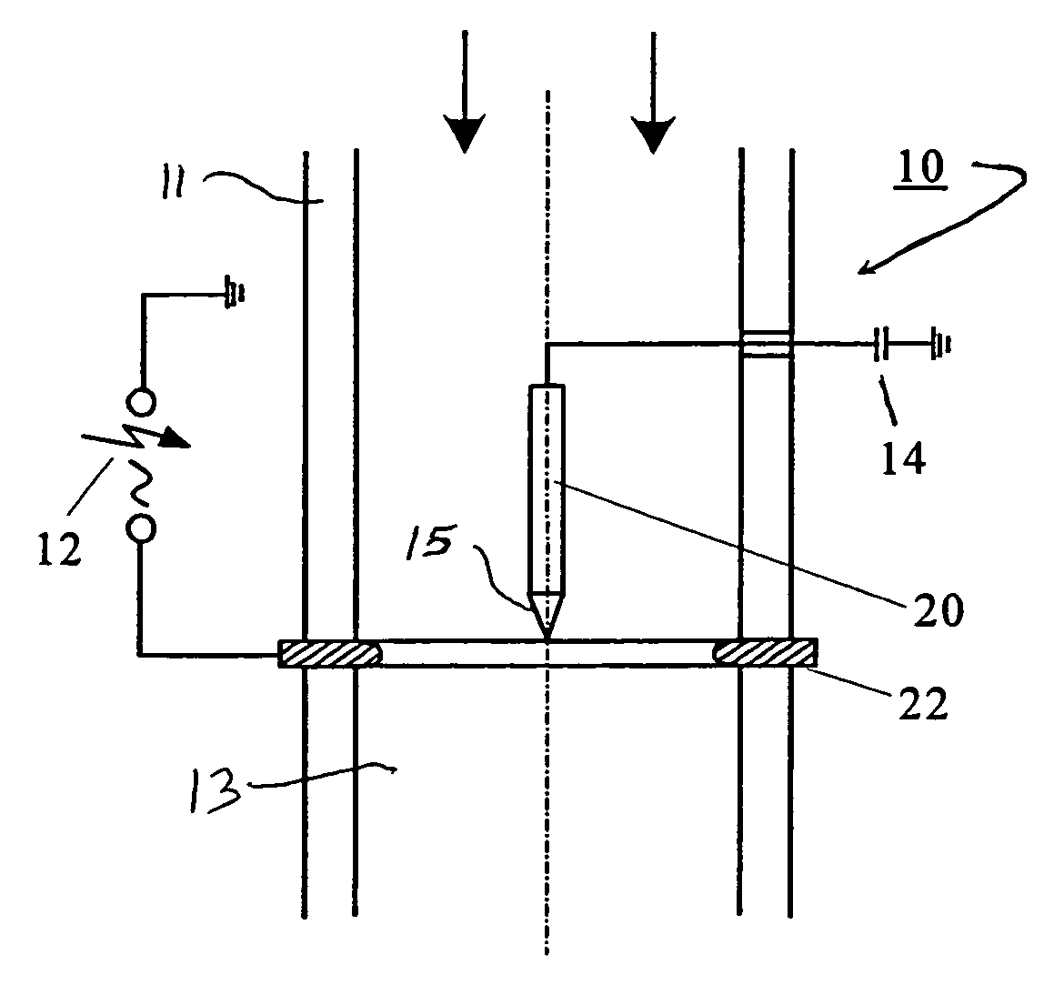
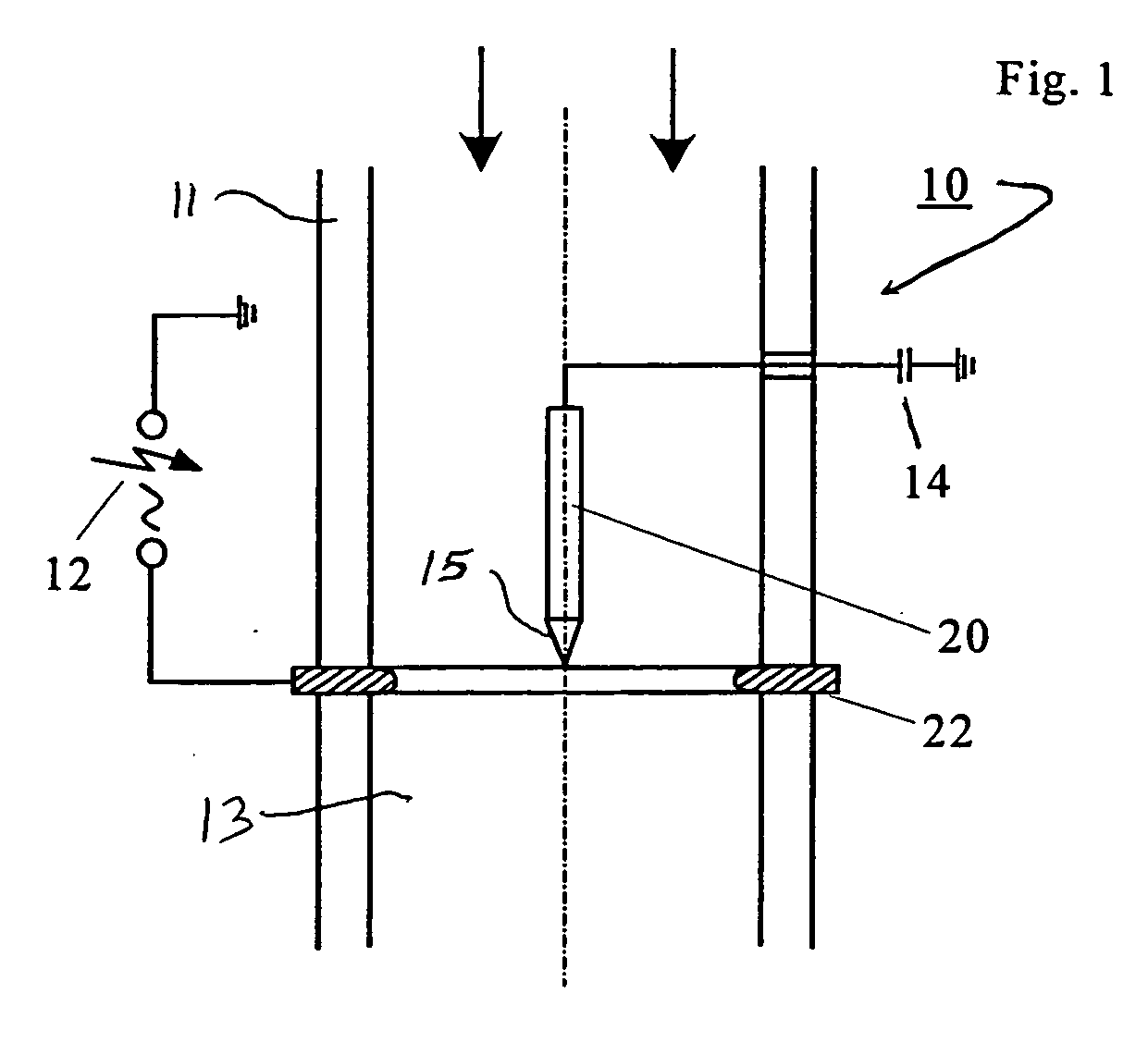
[0074]FIG. 1 shows a typical layout of an aerosol charge altering apparatus 10. The apparatus includes a tubular body or casing 11 forming a channel 13 to provide a flow path to guide an aerosol through the apparatus in the direction indicated by the arrows. An active electrode 20, preferably a needle formed of stainless steel or other metal, is supported relative to the casing at the center of channel 13. Electrode 20 is elongate in the direction of aerosol flow. A sharp tip 15 is formed at the downstream end of electrode 20. An annular passive electrode 22, preferably formed of brass and having a thickness of about 0.2 mm in the aerosol flow direction, is fixed to casing 11 in concentric surrounding relation to active electrode 20.

[0075] Electrodes 20 and 22 are electrically isolated from one another. Circuitry associated with the electrodes includes an alternating voltage supply 12 coupled to passive electrode 22, and a grounded capacitor 14 coupled to active electrode 20.

[0076...


PUM


Abstract

The invention relates to a device for charging or adjusting the charge of gas-borne particles into a defined charge distribution under utilization of corona discharge in the aerosol space. In addition to an appropriate geometry of the charger and the electrodes, the voltage waveform and the voltage regulation are of great significance for the result. The application further relates to a method for operating the device.

Description

BACKGROUND OF THE INVENTION [0001] The invention relates to a device and a method for charging or charge reversing an aerosol into a defined charge state of a bipolar diffusion charging (e.g. symmetrical or equilibrium charge distribution according to Fuchs, N., On the Stationary Charge Distribution on Aerosol Particles in a Bipolar Ionic Atmosphere, Geofis. Pura Appl., Vol. 56, 1963, pp. 185-192) with the aid of an electrical discharge in the aerosol space. [0002] Alternatively, the device and method are suitable for setting a defined unipolar charge state of the aerosol. [0003] Technical aerosols in industry and research often exhibit a medium to high electrical charge. Neutralization enables the production of aerosols of a defined charge state. Above all in research and in aerosol measurement technology involving instruments such as a differential mobility analyzer (DMA), neutralization can be an indispensable prerequisite. In addition, with the aid of neutralization the probabil...

Claims


Application Information

Patent Timeline
IPC IPC(8): B03C3/38B03C3/68G01N15/02H01T23/00
CPCH01T23/00B03C2201/32B03C3/68B03C3/38
Inventor RIEBEL, ULRICHSTOMMEL, YVES G.
Owner TSI INC
Learn More