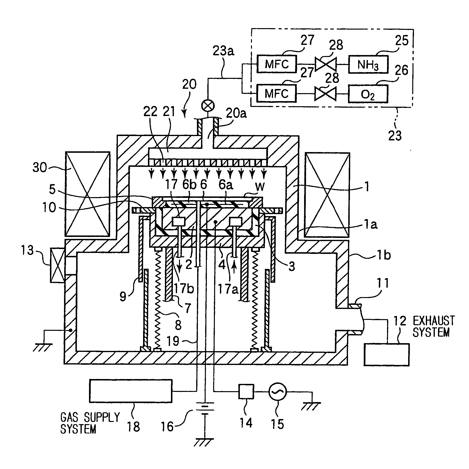
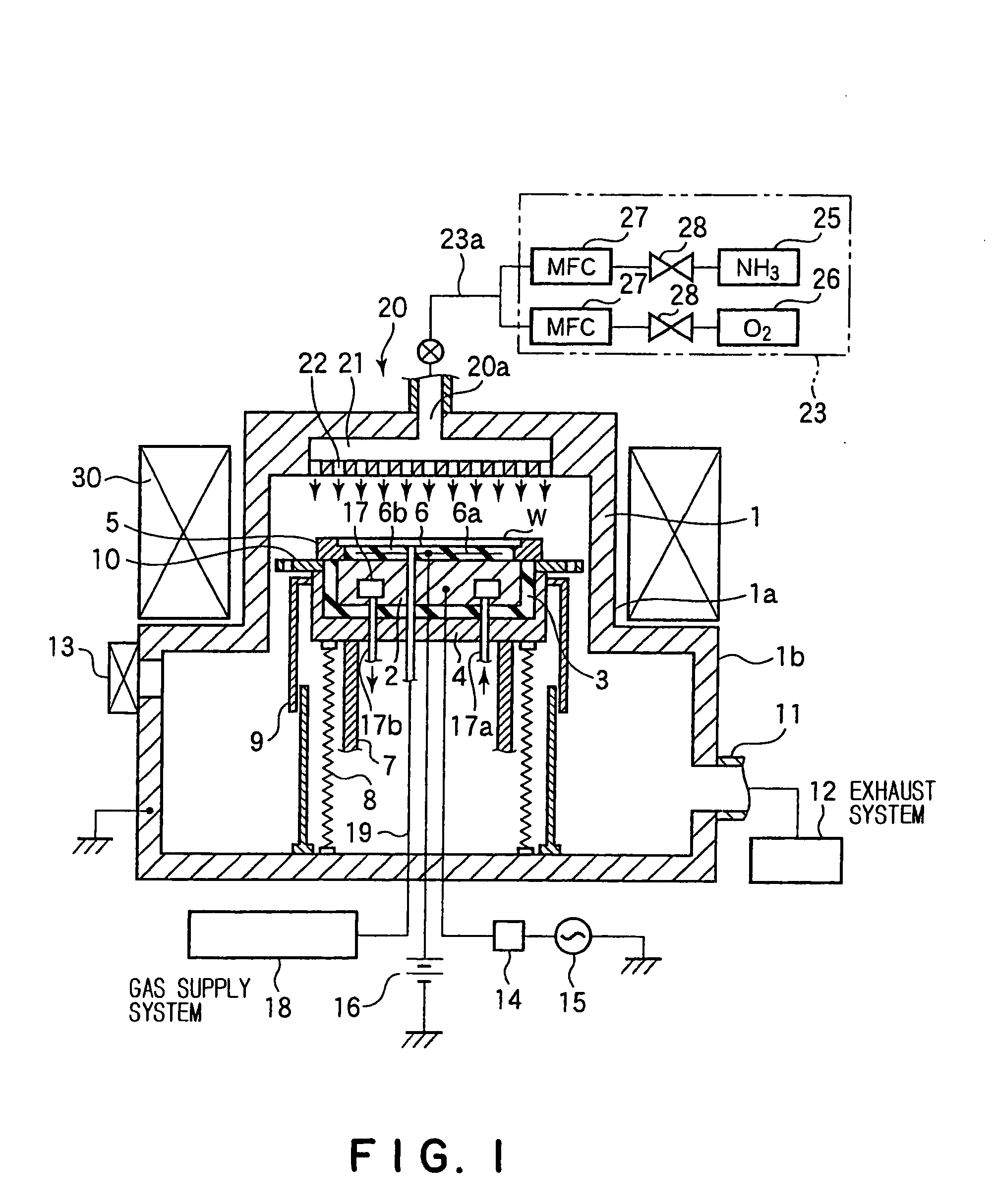
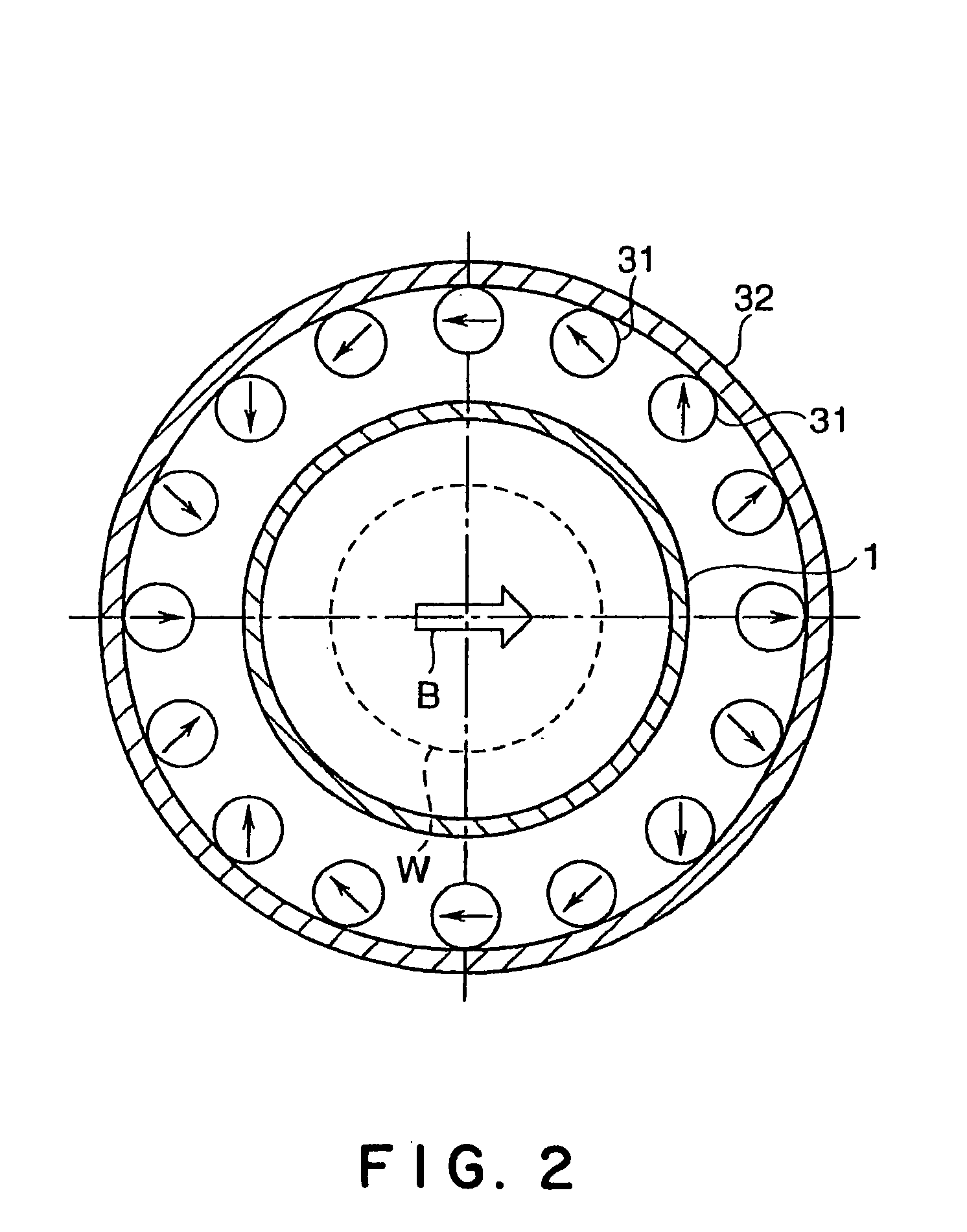
Etching method

a technology of etching method and resist film, which is applied in the direction of basic electric elements, semiconductor/solid-state device manufacturing, electric apparatus, etc., can solve the problem that the etching method cannot achieve a satisfactorily high etch rate of organic lower resist film, and the selectivity of the film to be etched relative to the resist film is not sufficient, etc. problem, to achieve the effect of high in-plane uniformity and high etch ra

Active Publication Date: 2005-04-21
TOKYO ELECTRON LTD +1
View PDF2 Cites 14 Cited by
  • Summary
  • Abstract
  • Description
  • Claims
  • Application Information

AI Technical Summary

Benefits of technology

[0009] The present invention has been made in view of the foregoing circumstances and it is therefore an object of the present invention to provide an etching method of etching an organic film by using an inorganic film as a mask, capable of etching the organic film in a pattern at a high etch rate in a satisfactory etch profile in a high in-plane uniformity without causing the inorganic film to come off.

Problems solved by technology

When a thin resist film is used to form a minute pattern, a film to be etched cannot be etched in a satisfactory profile.
Because an etching selectivity of the film to be etched relative to the resist film is not enough.
However, such an etching method could not etch the organic lower resist film at a satisfactorily high etch rate.
The technique disclosed in JP 1-280316 A, however, is incapable of achieving etching at a high etch rate for some combination of an etching gas and a pattern, the controllability of CD shift is unsatisfactory, the film is etched in a bowing shape, and in-plane etch uniformity is unsatisfactory.
These problems arise not only in etching a multilayer resist film, but also in etching an organic film by using an inorganic film as a mask.

Method used


Image

  • Etching method
  • Etching method
  • Etching method

Examples


experiment 1

[0077] Experiment 1 [0078] NH3 gas flow rate: 0.25 I / min [0079] O2 gas flow rate: 0.025 I / min [0080] Pressure in processing vessel: 2.7 Pa [0081] Residence time: 4.9 msec

[0082] Experiment 2 [0083] NH3 gas flow rate: 0.35 I / min [0084] O2 gas flow rate: 0.035 I / min [0085] Pressure in processing vessel: 4.0 Pa [0086] Residence time: 5.2 msec.

experiment 3

[0087] Experiment 3 [0088] NH3 gas flow rate: 0.43 I / min [0089] O2 gas flow rate: 0.043 I / min [0090] Pressure in processing vessel: 5.4 Pa [0091] Residence time: 5.7 msec.

[0092] Experiment 4 [0093] NH3 gas flow rate: 0.10 I / min [0094] O2 gas flow rate: 0.010 I / min [0095] Pressure in processing vessel: 2.7 Pa [0096] Residence time: 12.2 msec

[0097] FIGS. 8(a) to 8(d) show the results of Experiments 1 to 4, respectively. In Experiments 1 to 3, residence times were as short as about 5 msec and hence the organic films were etched at high etch rates exceeding 300 nm / min in satisfactory in-plane uniformity. In Experiment 4, residence time was longer than 10 msec and hence the organic film was etched at a low etch rate of 253.2 nm / min and the etched organic film had a low in-plane uniformity. The organic film etched by Experiment 2, in which residence time was 5.2 msec, had the highest in-plane uniformity among those etched by Experiments 1 to 3.

[0098] Experiments were conducted to study...

experiment 2

[0102] Experiment 2

[0103] NH3 gas and O2 gas were supplied at 0.35 I / min and 0.045 I / min, respectively, the O2 gas concentration of the etching gas was 11.4% and residence time was 5.1 msec.

[0104] Experiment 3

[0105] NH3 gas and O2 gas were supplied at 0.25 I / min and 0.050 I / min, respectively, the O2 gas concentration of the etching gas was 16.7% and residence time was 6.7 msec.

[0106] Results of experiments were as follows.

[0107] Experiment 1 [0108] Etch rate: 352.7 nm / min [0109] In-plane uniformity: ±1.7 [0110] CD shift in dense pattern: −1 nm (center), 5 nm (edge) [0111] CD shift in sparse pattern: 14 nm (center), 19 nm (edge).

[0112] Experiment 2 [0113] Etch rate: 355.1 nm / min [0114] In-plane uniformity: ±1.3 [0115] CD shift in dense pattern: 3 nm (center), 6 nm (edge) [0116] CD shift in sparse pattern: 15 nm (center), 20 nm (edge).

[0117] Experiment 3 [0118] Etch rate: 350.9 nm / min [0119] In-plane uniformity: ±3.3 [0120] CD shift in dense pattern: 0 nm (center), 1 nm (edge) [...


PUM


Abstract

An etching method etches an organic film by using an inorganic film as a mask at a high etch rate, in a satisfactory etch profile in a satisfactory in-plane uniformity without causing the inorganic film to peel off. An organic film formed on a workpiece is etched by using an inorganic film as a mask with a plasma produced by discharging an etching gas in a processing vessel (1). The etching method uses a mixed gas containing NH3 gas and O2 gas for etching the organic film when the organic film is to be etched in a pattern having an opening ratio of 40% or above. The etching method uses NH3 gas as an etching gas for etching the organic film when the organic film is to be etched in a pattern having an opening ratio below 40%.

Description

TECHNICAL FIELD [0001] The present invention relates to an etching method of plasma-etching an organic film formed on a workpiece, such as a semiconductor wafer, using a mask formed by patterning an inorganic film. BACKGROUND ART [0002] Further increase in the number of component parts per semiconductor device has been desired in recent years, and the formation of further minute patterns has been required accordingly. To meet such a requirement, a photolithographic process needs to form a thin resist film on a semiconductor wafer to form a minute pattern of a high resolution by a dry etching process. [0003] When a thin resist film is used to form a minute pattern, a film to be etched cannot be etched in a satisfactory profile. Because an etching selectivity of the film to be etched relative to the resist film is not enough. [0004] A conventional technique uses a multilayer resist film to solve such a problem. A multilayer resist film, for example, consists of a lower resist film of ...

Claims


Application Information

Patent Timeline
Patent Type & Authority Applications(United States)
IPC IPC(8): H01L21/3065H01L21/302H01L21/311H01L21/461
CPCH01L21/31138H01L21/31116H01L21/31144H01L21/3065H01L21/31H01L21/32
Inventor OGAWA, KAZUTOINAZAWA, KOICHIROHAYASHI, HISATAKAOHIWA, TOKUHISAINAZAWA, RIE
Owner TOKYO ELECTRON LTD
Why Eureka
Try Eureka