Particle formation

a particle and particle technology, applied in the field of particle formation, can solve the problem that authors have not appeared to have achieved such high velocities

Inactive Publication Date: 2005-04-21
NEKTAR THERAPEUTICS UK LTD
View PDF5 Cites 12 Cited by
  • Summary
  • Abstract
  • Description
  • Claims
  • Application Information

AI Technical Summary

Benefits of technology

[0024] The desired anti-solvent velocity is ideally achieved simply by the use of appropriate anti-solvent flow rates, back pressures and / or operating temperatures, and without the aid of mechanical, electrical and / or magnetic input such as for example from impellers, impinging surfaces especially within the anti-solvent inlet, electrical transducers and the like. Introducing the anti-solvent via a convergent nozzle, ideally as a single fluid stream, may also help in the achievement of appropriate fluid velocities. Further “energising” fluid streams, such as those required in the method of WO-97 / 31691, are not then needed in order to achieve the desired level of control over the contact between the target solution / suspension and the anti-solvent fluid.
[0084] It is believed, although we do not wish to be bound by this theory, that there may be an optimum separation between the two outlets which represents a balance between avoiding undue agglomeration of the particles as they form whilst also maximising the efficiency of fluid mixing and vehicle extraction. If the target solution / suspension is introduced into the anti-solvent flow close to the outlet of the second fluid inlet, then fluid mixing will be highly efficient and particle formation rapid, but there may also be an increased tendency for agglomeration of the particles as they form, resulting ultimately in a larger diameter product. Conversely, if the two fluids meet at too great a distance from the outlet of the second fluid inlet, then fluid mixing and vehicle extraction may be less efficient, reducing control over the product characteristics (including particle size and morphology), potentially allowing more particle growth and higher residual solvent levels and possibly also reducing yields.

Problems solved by technology

However, the authors do not appear ever to have achieved such high velocities in their experimental examples.

Method used


Image

  • Particle formation
  • Particle formation
  • Particle formation

Examples


examples a

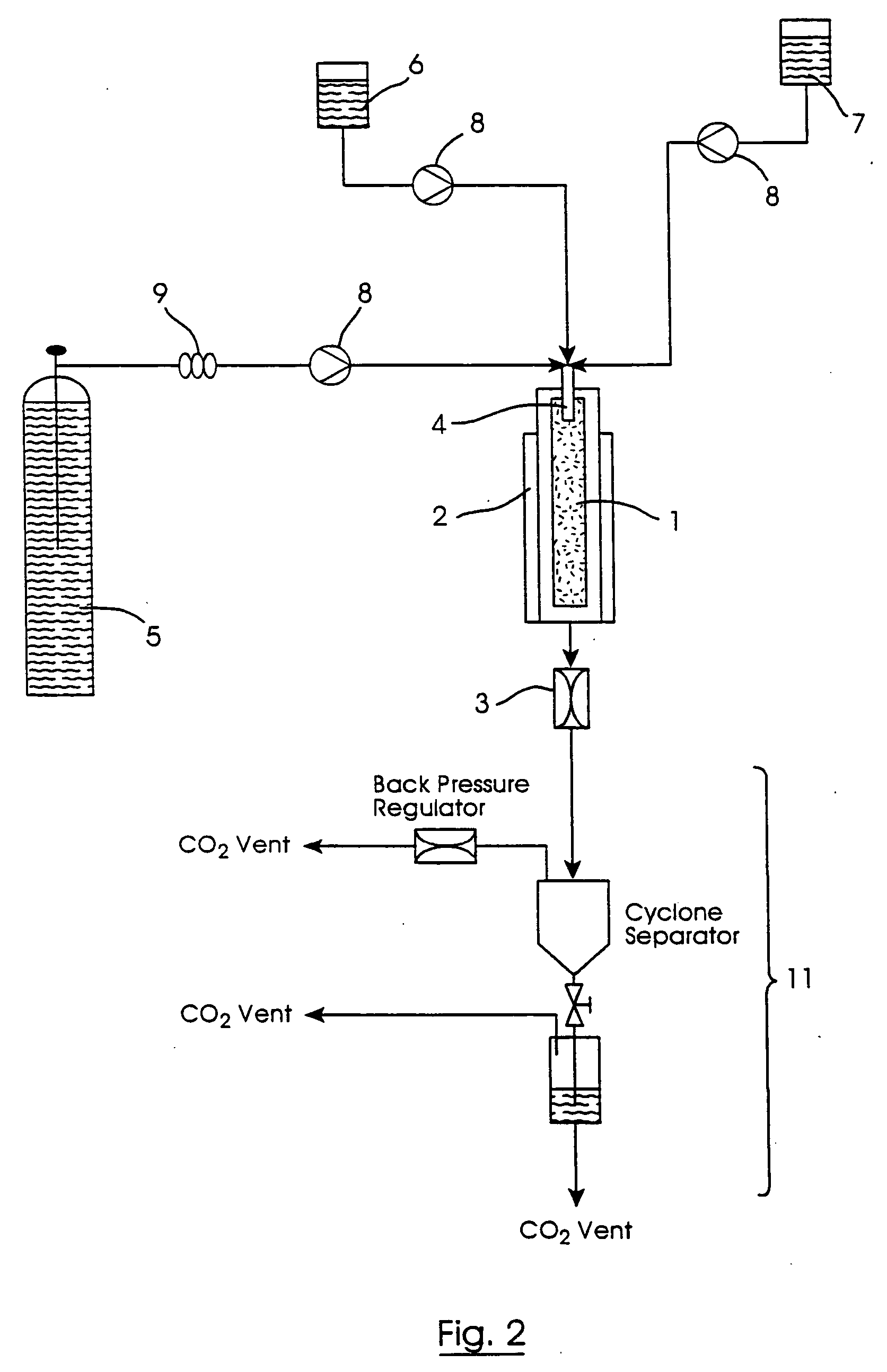
[0115] Apparatus as shown in FIG. 2, incorporating a fluid inlet assembly as shown in FIGS. 3 to 5, was used to carry out particle formation methods in accordance with the invention.

[0116] The nozzle 21 comprised a fluid inlet tube of internal diameter 0.75 mm, a convergent tip with a 60° half angle taper (with respect to the central longitudinal nozzle axis) and an outlet of diameter 0.2 mm. According to theory, this generates a fluid jet with a cone angle of approximately 20°.

[0117] The internal bore at the end of the inlet tube 23 was 0.125 mm.

[0118] The experiments investigated the effect of varying both (a) the horizontal distance x between the solution line outlet and the central axis of anti-solvent flow, and (b) the vertical distance y between the nozzle outlet 22 and the solution line outlet (y being measured, for convenience, from the top external wall of the solution inlet tube 23).

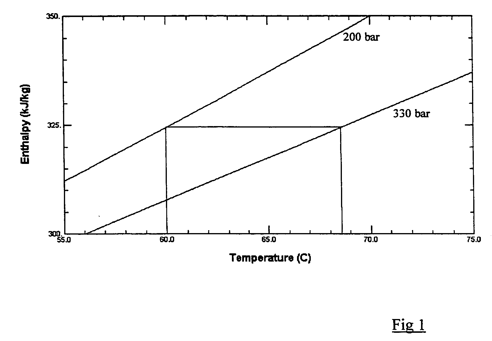
[0119] Supercritical carbon dioxide, pre-heated to 70° C., was used as the anti-solvent...

examples b

[0127] Apparatus as shown in FIG. 2, incorporating a fluid inlet assembly as shown in FIGS. 6 and 7, was used to carry out a further particle formation method in accordance with the invention. The nozzle 21 was the same as used in Examples A.

[0128] The target solution inlet comprised a fused silica capillary of length 20 mm and internal diameter 50 μm, glued into a standard 1.59 mm ({fraction (1 / 16)}″) internal diameter stainless steel tube. Its outlet, into the particle formation vessel 1, was therefore 50 μm in diameter, and its cross sectional area only 6% of that of the outlet of nozzle 21. A two-component epoxy resin was used to secure the capillary in place, under elevated temperatures (180° C.) to enhance the mechanical strength of the bond. Due to the viscous flow of the uncured resin, it was not possible to centre the capillary within the stainless steel tube.

[0129] The vertical separation “y” was ˜0.5-1 mm.

[0130] Again supercritical carbon dioxide was used as the anti-s...

examples d

[0140] Examples A were repeated, using the same nozzle 21 but with a 0.4 mm diameter outlet.

[0141] The vertical distance y between the nozzle outlet 22 and the solution tube outlet was varied between 4 and 8 mm. The solution tube outlet was positioned in line with the nozzle outlet (ie, x=0 mm).

[0142] The supercritical carbon dioxide anti-solvent was pumped at a flow rate of 200 ml / min. The salmeterol solution flow rate was 4 ml / min. The vessel temperature and pressure were as in Examples A, and the CO2 velocity at the nozzle outlet 22 was sub-sonic throughout the experiments. The run time for each experiment was approximately one hour.

[0143] Product particle sizes were measured using a Sympatec™ apparatus at 2 bar shear pressure.

[0144] The results are shown in Table 4.

TABLE 4YieldParticleParticleExpt.(%sizesizeno.y (mm)w / w)(μm)*spread**D144911.75 ± 0.05 2.25D2649 8.6 ± 0.032D38498.65 ± 0.012.04

*Volume mean diameter, representing the average of two analyses.

**Particle size sp...


PUM

PropertyMeasurementUnit
diameteraaaaaaaaaa
angleaaaaaaaaaa
diameteraaaaaaaaaa

Abstract

Method for preparing a target substance in particulate form, by introducing into a particle formation vessel, through separate first and second fluid inlets respectively, (a) a solution or suspension of the target substance in a fluid vehicle (the “target solution / suspension”) and (b) a compressed fluid anti-solvent for the substance, and allowing the anti-solvent to extract the vehicle from the target solution / suspension so as to form particles of the target substance, wherein the target solution / suspension enters the vessel downstream of the point of entry of the anti-solvent and at a point which lies on or close to the main axis of anti-solvent flow, and wherein the anti-solvent has a sub-sonic velocity as it enters the particle formation vessel.

Description

FIELD OF THE INVENTION [0001] This invention relates to methods for use in forming particles of a target substance, and to their particulate products. BACKGROUND OF THE INVENTION [0002] It is known to use a compressed fluid, typically a supercritical or near-critical fluid, as an anti-solvent to precipitate particles of a substance of interest (a “target substance”) from solution or suspension. The basic technique is known as “GAS” (Gas Anti-Solvent) precipitation [Gallagher et al, “Supercritical Fluid Science and Technology”, ACS Symp. Ser., 406, p334 (1989)]. Versions of it have been disclosed for instance in EP-0 322 687 and WO-90 / 03782. [0003] In one particular version known as the Nektar™ SCF particle formation process (previously known as SEDS™ or “Solution Enhanced Dispersion by Supercritical fluids”), a target substance is dissolved or suspended in an appropriate fluid vehicle, and the resulting “target solution / suspension” then co-introduced into a particle formation vessel...

Claims


Application Information

Patent Timeline
Patent Type & Authority Applications(United States)
IPC IPC(8): B01D11/04B01J2/04
CPCB01D11/0411B01J2/04B01D11/0407B01D11/0403B01D11/0473B01D11/0484
Inventor KORDIKOWSKI, ANDREASGILBERT, DARREN JOHN
Owner NEKTAR THERAPEUTICS UK LTD
Why Eureka
Try Eureka