Information recording method and apparatus with suppressed mark edge jitters

a mark edge jitter and information recording technology, applied in the field of information recording methods and apparatuses with suppressed mark edge jitters, can solve the problems of thermal interference to adjacent tracks, erase information recorded in adjacent tracks, etc., and achieve the effect of high density

Inactive Publication Date: 2005-04-28
HITACHI CONSUMER ELECTRONICS CORP
View PDF10 Cites 4 Cited by
  • Summary
  • Abstract
  • Description
  • Claims
  • Application Information

AI Technical Summary

Benefits of technology

[0005] The object of the present invention is to provide an information recording method and apparatus capable of recording information with high density.
[0007] On the other hand, a technique for reducing the track pitches is under development with the intention of increasing the recording density. A method exists, for example, in which information is recorded in both grooves and lands (areas between grooves) formed on an information recording medium. According to this method, crosstalks of reproduced signals from lands to grooves or from grooves to lands can be cancelled by setting the grooves to a proper depth (optical phase difference between lands and grooves).

Problems solved by technology

Therefore, thermal interferences occur to adjacent tracks (grooves adjacent to lands or lands adjacent to grooves) in the case where the energy beam position cannot be controlled in stable fashion.
This leads to the problem that the information recorded in adjacent tracks is erased.

Method used


Image

  • Information recording method and apparatus with suppressed mark edge jitters
  • Information recording method and apparatus with suppressed mark edge jitters
  • Information recording method and apparatus with suppressed mark edge jitters

Examples


Embodiment Construction

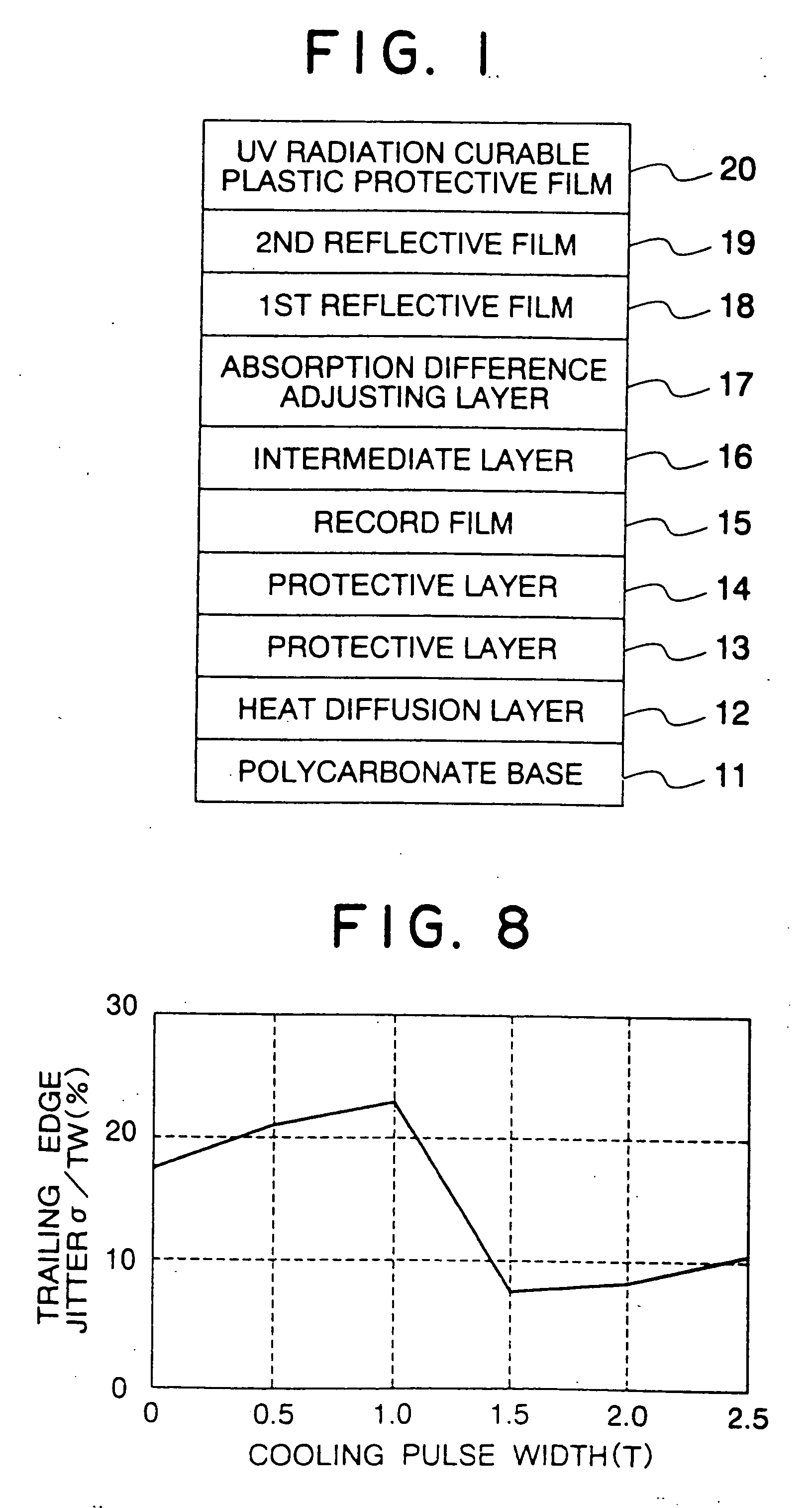
[0032]FIG. 1 shows a sectional structure of a disk-shaped information recording medium according to an embodiment. This medium can be fabricated in the following manner.

[0033] First, a polycarbonate base 12 cm in diameter and 0.6 mm in thickness having tracking guide grooves for land / groove recording at ditches of 0.6 μm in the surface thereof is formed with an Al2O3 heat diffusion layer 12 about 30 nm thick. An 80ZnS-20SiO2 protective layer 13 about 45 nm thick is formed. A SiO2 protective layer 14 about 5 nm thick is formed. Then, a Ge14Sb28Te58 record film 15 about 15 nm thick and a SiO2 intermediate layer 16 about 5 nm thick are formed. Further, an absorption difference adjusting layer 17 about 18 nm thick made of an 80Mo-20SiO2 film is formed, followed by a first reflective layer 18 of 89Al-11Ti about 70 nm thick and a second reflective layer 19 of 97Al-3Ti film about 70 nm thick, in that order. A layered film can be formed by a magnetron sputtering device. A protective film 2...


PUM

PropertyMeasurementUnit
thicknessaaaaaaaaaa
thicknessaaaaaaaaaa
diameteraaaaaaaaaa

Abstract

A method for recording information is disclosed in which an information recording medium is irradiated with a recording energy beam power-modulated into at least a record power level and a record-ready power level lower than the record power level. When forming a mark portion of a predetermined length, the radiation energy of the energy beam is increased as compared with when forming a mark portion of a different length before or after the first pulse of an energy beam pulse train including at least a pulse for forming the mark portion. Also, only in the case where the energy beam is modulated by the power lower in power level than the record-ready power level after the last pulse of the energy beam pulse train including at least one pulse for forming a mark portion and the mark portion is followed by a space portion of a predetermined length, the particular radiation energy of low power level is reduced as compared with when the mark portion is followed by a space potion of a different length. The radiation energy is increased and / or decreased.

Description

BACKGROUND OF THE INVENTION [0001] The present invention relates to a method and apparatus for recording information in an information recording medium by radiation of an energy beam, or more in particular to an information recording method very effective for a phase change optical disk and an information recording apparatus using such an information recording method. [0002] A conventional method of recording and erasing information in a rewritable record film is disclosed, for example, in JP-A-62-175948 (laid open Aug. 1, 1987), which uses a magneto-optical disk of an exchange couple double-layered film as a record film. Another conventional method for recording and erasing information in a rewritable record film is disclosed in JP-A-62-259229 (laid open Nov. 11, 1987), which uses a record film for a phase change optical disk capable of high-speed erasure by crystallization within substantially the same time as the laser radiation time for recording. In these cases, the power of an...

Claims


Application Information

Patent Timeline
Patent Type & Authority Applications(United States)
IPC IPC(8): G11B5/09G11B7/00G11B7/004G11B7/0045G11B7/0055G11B7/006G11B7/125G11B7/126G11B20/10G11B20/14
CPCG11B7/00454G11B7/00557G11B7/006G11B20/1426G11B7/126G11B20/10009G11B7/0062G11B7/00
Inventor MIYAMOTO, MAKOTOTODA, TSUYOSHIOHTAKE, MASATOSHITERAO, MOTOYASUUSHIYAMA, JUNKOANDOO, KEIKICHIANZAI, YUMIKOHIROTSUNE, AKEMINISHIDA, TETSUYASAGA, HIDEKI
Owner HITACHI CONSUMER ELECTRONICS CORP
Why Eureka
Try Eureka