Underground exploration apparatus, system and method

a technology of underground exploration and equipment, applied in the field of measurement equipment, can solve the problems of inability the inability of the acoustic exploration method to detect the depth of an underground stream and the presence of underground resources, and the inability of the acoustic exploration method to find the substance of the geological layer

Inactive Publication Date: 2005-05-05
CANON KK
View PDF4 Cites 28 Cited by
  • Summary
  • Abstract
  • Description
  • Claims
  • Application Information

AI Technical Summary

Benefits of technology

[0050] According to a fifth aspect of the present invention, there is provided an underground exploration system including: an oscillator 1 capable of selecting among two or more fundamental oscillation frequencies; a voltage-current converter 2 for converting a voltage signal generated by the oscillator 1 into current; a pair of electrodes 3 placed on or buried in the ground apart from each other in order to conduct a current supplied by the voltage-current converter 2 through the ground; a measuring unit 4 for measuring a voltage generated between both ends of the electrodes 3 to detect an impedanc

Problems solved by technology

A drawback of acoustic exploration is that the method cannot find an unknown substance in a geological layer where the density is approximately uniform and no oscillatory waves are reflected.
In short, in the acoustic exploration method, it is possible to provide the depth and thickness of a geological layer, but it is not possible to find what substances the geological layer is made of unless a proper drilling survey is conducted.
For instance, the acoustic exploration method is incapable of detecting the depth of an underground stream and the presence of underground resources or measuring whether or not the soil is contaminated by chemicals.
A drawback of the X-ray backscattering method is to explore only areas near the ground surface when the soil has high water content.
Another drawback of this method is to be incapable of identifying the geological condition.
The m

Method used


Image

  • Underground exploration apparatus, system and method
  • Underground exploration apparatus, system and method
  • Underground exploration apparatus, system and method

Examples


embodiment 1

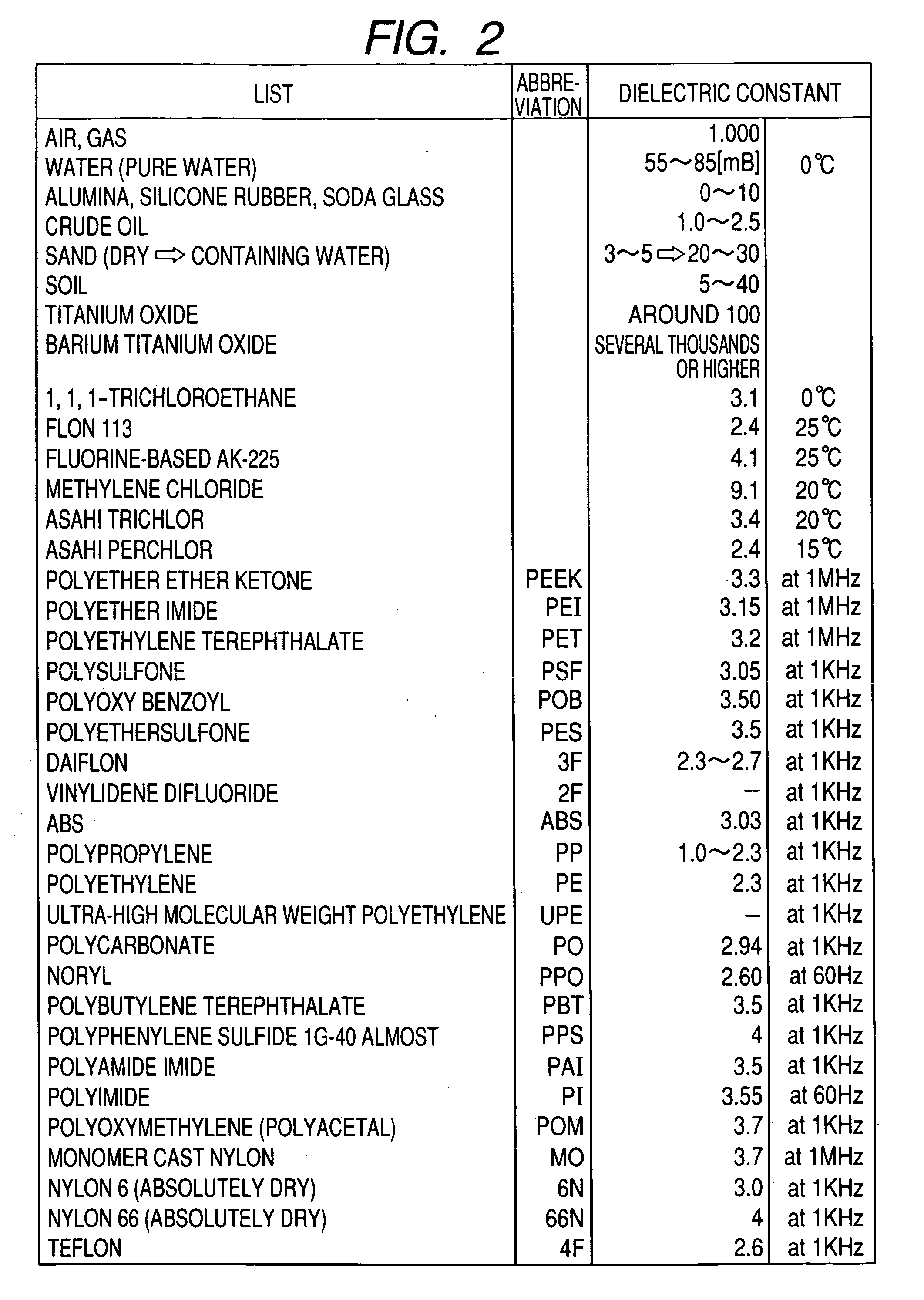
[0091]FIG. 2 is a table showing the fact that substances constituting the ground, chemicals, and the like have different specific dielectric constants, which forms the basis of the measurement principle of the present invention. Specific dielectric constant is a coefficient indicating the readiness of a corresponding substance to polarize in relation to the vacuum dielectric constant. An actual dielectric constant ε can be obtained by multiplying the vacuum dielectric constant by the specific dielectric constant of the substance. The dielectric constant generally fluctuates depending on the frequency and temperature employed in the measurement.

[0092]FIG. 3 is a diagram illustrating the frequency dependency of the dielectric constant and fluctuation factors thereof. The dielectric constant is a coefficient indicating the readiness to polarize. There are four known types of polarization of a substance: interface polarization, dipole polarization, ion polarization, and electronic pola...

embodiment 2

[0100]FIG. 9 is a diagram illustrating a detailed structure of an oscillator 1 according to another embodiment of the present invention. There are various electric currents flowing under the ground that can be disturbances to AC tests. Such electric currents include one accompanying movement of static electricity build up in the ground, one flowing back from a power transmission line or railway's overhead wire through the ground, one leaked from an electric appliance, and the like. In order to detect a minuscule change in impedance without being influenced by those currents, it is preferable to use an oscillator structured as shown in FIG. 9.

[0101] A sine-wave generator shown in FIG. 9 generates a sine wave to supply the signal to a multiplier and, in addition, supplies a clock signal to an M-sequence generator in sync with a fundamental frequency. The M-sequence generator is an electronic circuit for generating a maximum length code sequence (M-sequence code), which is a binary co...

embodiment 3

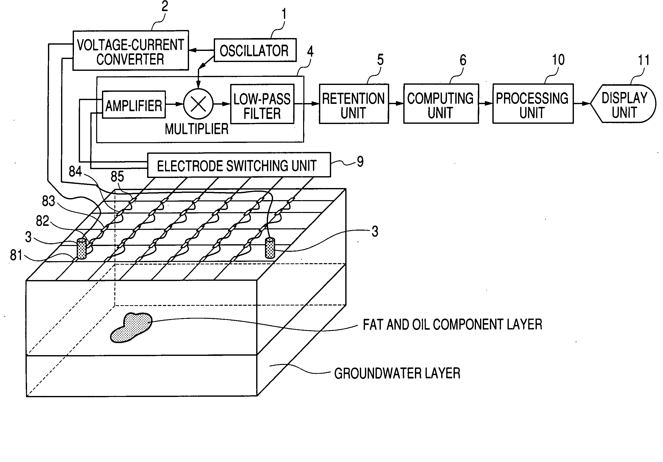
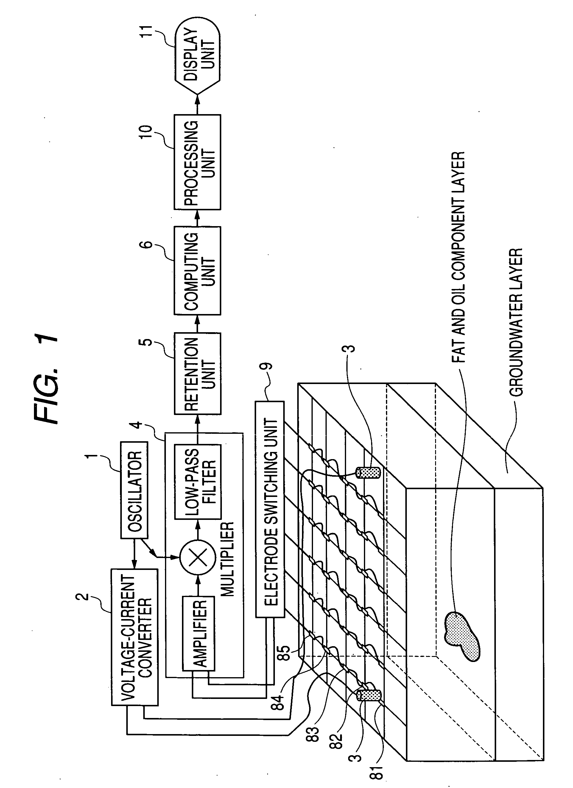
[0104]FIG. 1 is a diagram showing the structure of an underground exploration apparatus according to a still another embodiment of the present invention. In FIG. 1, a transmitter waveform generated by the oscillator 1 is converted into current by the voltage-current converter 2 and then conducted to the ground via the ends of the pair of current application electrodes 3. As a result of the current conduction, a high frequency voltage generated between two arbitrary electrodes chosen out of the voltage measurement electrodes 81, 82, 83, 84, . . . , 8N in a total number of N, which are provided to measure a high frequency voltage induced on the ground surface, is supplied to an amplifier via the electrode switching unit 9. The high frequency voltage is multiplied in sync with the transmitted wave, and passed through a low pass filter for synchronous detection processing. The measuring unit 4 composed of the amplifier, the multiplier, and the low pass filter serves as a synchronous det...


PUM


Abstract

The object of the present invention is to realize a low-invasive underground exploration apparatus, system, and method which are capable of specifying the kind, three-dimensional position, and amount of a substance present in the ground. The underground exploration apparatus, system, and method includes: measuring, at multiple points, a high frequency voltage that appears upon conduction of high frequency current through the ground to obtain measurement results at two or more frequency levels; employing an ground model using the finite element method, the boundary element method, an impedance network, or the like to estimate a substance in the ground by changing unknown quantities of the ground model such as local dielectric constant and electric conductivity so as to make an error between the actual measured value and the calculated value smaller; and displaying input information of the ground model and results of the estimation processing two-dimensionally or three-dimensionally.

Description

[0001] This application is a continuation of International Application No. PCT / JP2004 / 010446, filed Jul. 15, 2004, which claims the benefit of Japanese Patent Application No. 2003-197537 filed on Jul. 16, 2003.BACKGROUND OF THE INVENTION [0002] 1. Field of the Invention [0003] The present invention relates to a measurement apparatus which uses low-invasive, alternating current testing means to survey and observe the status of an underground water leakage, the location, geometry, depth, and amount of underground streams and resources or of soil contaminants, and the progress of soil improvement. More specifically, the present invention relates to an underground exploration apparatus which measures at multiple points a voltage generated by conducting electric current through the ground to obtain measurement results at two or more frequencies, which uses an ground model that employs the finite element method or the boundary element method, an impedance network, or the like, which chang...

Claims


Application Information

Patent Timeline
IPC IPC(8): G01N27/04G01V3/06
CPCG01V3/06G01N27/043
Inventor UEDA, TOMOAKINAKAMURA, KAZUHITOKISHIMOTO, YUKIOICHIMURA, NAOYAYASUDA, TOKUGEN
Owner CANON KK
Why Eureka
Try Eureka