Immobilized enzymes in biocathodes

a biocathode and enzyme technology, applied in the field of biocathodes, can solve the problems of low volumetric catalytic activity of the whole organism, impractical power density output, nafion® has not been successful at immobilizing enzymes at the surface of biofuel cell electrodes,

Inactive Publication Date: 2005-05-05
SAINT LOUIS UNIVERSITY
View PDF40 Cites 121 Cited by
  • Summary
  • Abstract
  • Description
  • Claims
  • Application Information

AI Technical Summary

Problems solved by technology

Although early biofuel cell technology employed metabolic pathways of whole microorganisms, the problems associated with this approach include low volumetric catalytic activity of the whole organism and impractical power density outputs [Palmore and Whitesides, 1994, ACS Symposium Series 566:271-290].
Although enzymes are highly efficient catalysts, there have been problems incorporating them into fuel cells.
One of the main obstacles of enzyme-based biofuel cells has been to immobilize the enzyme in a membrane at the electrode surface that will extend the lifetime of the enzyme and form a mechanically and chemically stable layer, while not forming a capacitive region at the electrode surface.
However, Nafion® has not been successful at immobilizing enzymes at the surface of biofuel cell electrodes because Nafion® forms an acidic membrane that decreases the lifetime and activity of the enzyme.
Thus, the enzymes described in those disclosures have very limited stability, with a maximum activity lifetime of generally no more than 7 to 10 days.

Method used


Image

  • Immobilized enzymes in biocathodes
  • Immobilized enzymes in biocathodes
  • Immobilized enzymes in biocathodes

Examples


example 1

Preparation of Enzyme-Immobilized Salt-Extracted Membranes

Preparation of Ru(bpy)3+2 / Nafion I

[0188] Ru(bpy)3+2 / Nafion I is made by the direct addition of Ru(bpy)3+2 salt to Nafion suspension (mixture casting).

[0189] To prepare the Ru(bpy)3+2 / Nafion I Salt-Extracted Membrane (“Nafion I”), 0.15 millimols of Ru(bpy)3+2 were added to 4 ml of Nafion®), mixed well for ˜3 to 4 hours by vortexing and using a sonicator in a constant temperature water bath. The mixture was then poured into a weighing boat to dry overnight. Once dry, the Ru(bpy)3+2 / Nafion® mixture was salt extracted by soaking into deionized water using vortex, followed by centrifugation. The extracted solution went from orange to clear when all salt is extracted. The salt-extracted membrane was rinsed and dried, then redissolved in 4 ml of 80% Ethanol (can be redissolved in a mixture of lower aliphatic alcohols containing up to 30% water).

[0190] The cathode enzyme was immobilized in the Ru(bpy)3+2 / Nafion I Salt-Extracted ...

example 2

Preparation of Electrodes

Preparation of Ru(bpy)3+2 / Nafion III on glassy carbon electrodes

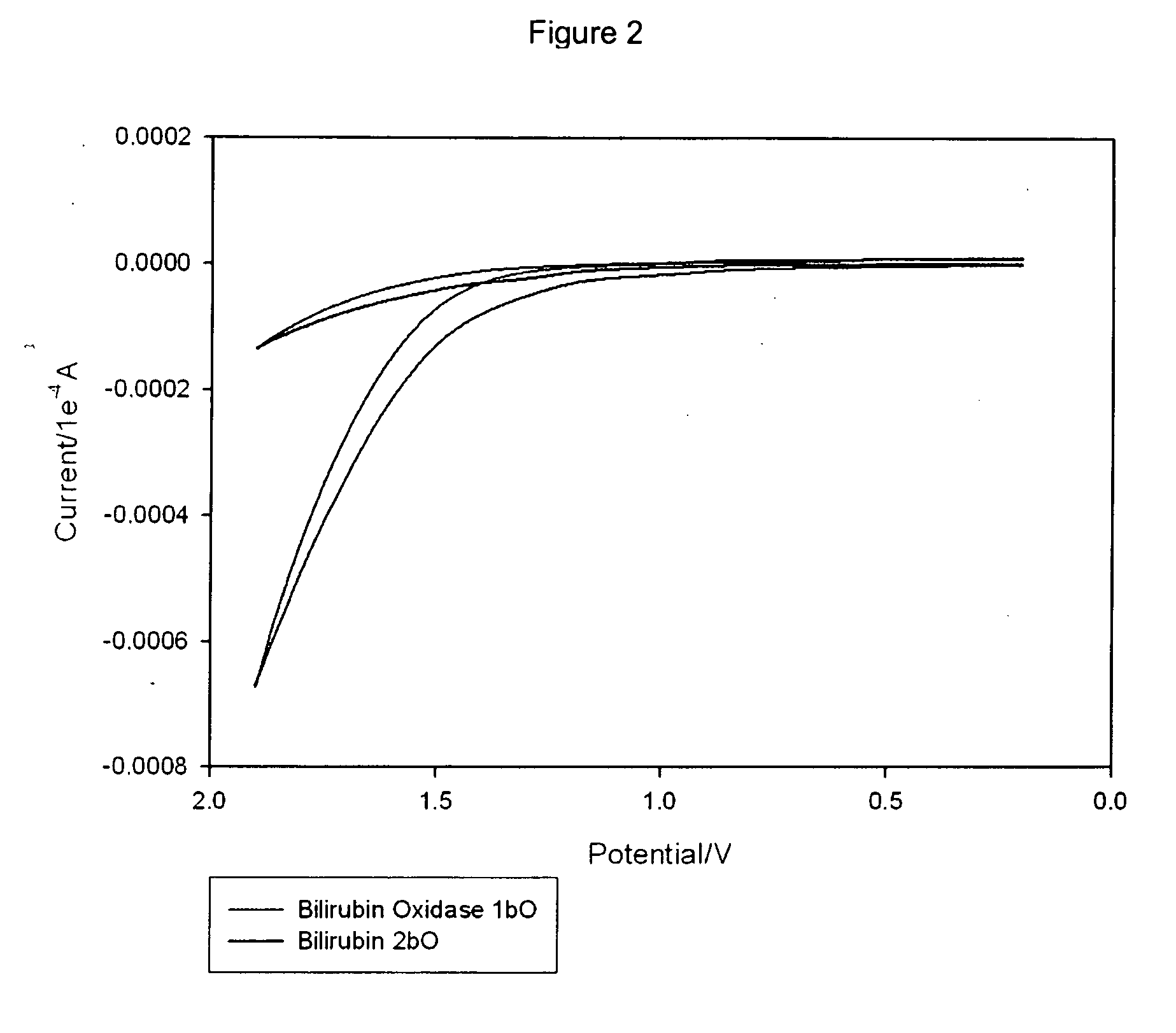
[0196] To prepare the cathode enzyme / membrane casting solution, ˜1 mg of Bilirubin and ˜0.5-1 mg of Bilirubin Oxidase were added to 100 ml Ru(bpy)3+2 / Nafion III Salt-Extracted Membrane (supra) and mixed well (in this case, vortexed for 20 minutes). 2 ml of the cathode enzyme / membrane casting solution was applied to polished glassy carbon electrodes (3 mm in diameter) and allowed to dry. Once dry, the cathode enzyme / membrane / carbon electrode was soaked for 3 h in a N2-degassed Ru(bpy)3+2 solution. After the exchange of TBAB for Ru(bpy)3+2, the carbon electrodes were introduced into a N2-degassed Phosphate buffer of pH 7.4 and allowed to soak for 1 h. After equilibration, the cathodes were tested by cyclic voltammetry at scan rates of 0.05 and 0.1 V / s. Then, the buffer solution was saturated with O2 for 10 min and the cathodes were tested as above.

Preparation of Ru(bpy)3+2 / Nafion III on 1 cm2...

example 3

Biofuel Cell

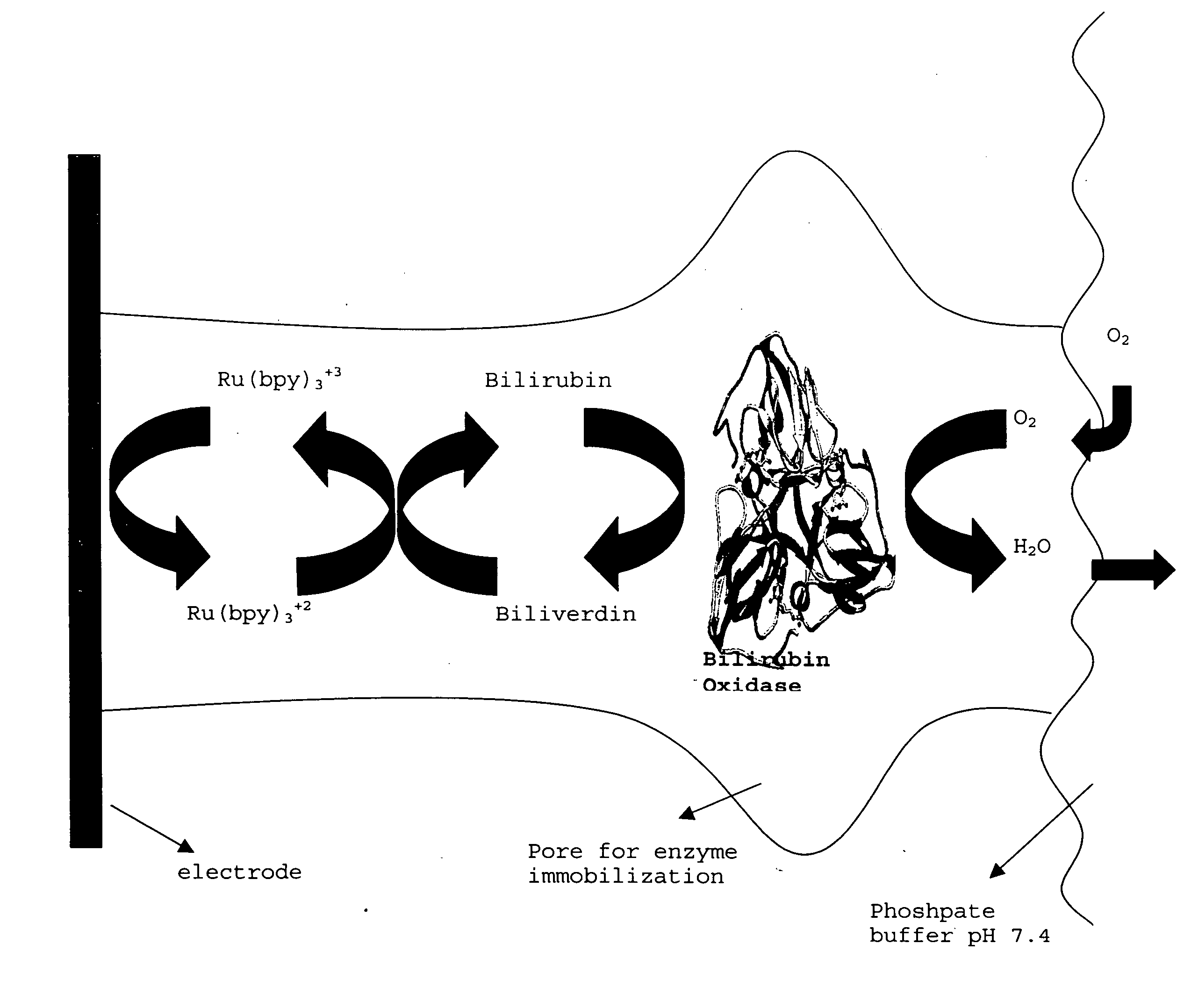
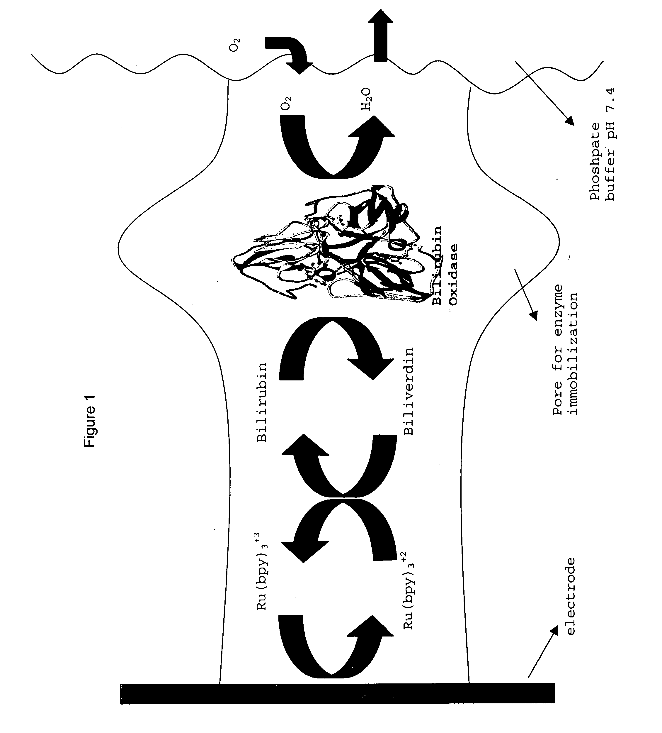
[0200] A prototype biofuel cell (FIG. 11) was built comprising a bioanode, which comprises an alcohol dehydrogenase immobilized in TBAB-modified Nafion® (as described in patent applications 60 / 429,829, 60 / 486,076 and Ser. No. 10 / 617,452), and the instant Nafion III membrane comprising bilirubin oxidase, bilirubin and Ru(bpy)3+2 (see FIG. 1 for a depiction of the dual function biocathode membrane). Initial tests of this non-optimal biofuel cell, which has a PEM (Nafion® 117) membrane that separates the anode and cathode solutions and in which catalyst loading was only ˜28% of the membranes depicted in the voltammogram experiments (supra), indicated that the open circuit potentials ranged from 0.4179-0.819 Volts and the maximum current density ranged from 0.224 mA / cm2 to 2.23 mAmps / cm2 and the maximum power was 0.951 mW / cm2 (see FIG. 12, which depicts the power curve for this prototype).


PUM

PropertyMeasurementUnit
standard reduction potentialsaaaaaaaaaa
pHaaaaaaaaaa
diameteraaaaaaaaaa

Abstract

Disclosed is an improved biofuel cell having a cathode comprising a dual function membrane, which contains an oxygen oxidoreductase enzyme immobilized within a buffered compartment of the membrane and an electron transport mediator which transfers electrons from an electron conducting electrode to the redox reaction catalyzed by the oxygen oxidoreductase enzyme. The improved biofuel cell also has an anode that contains an oxidoreductase enzyme that uses an organic fuel, such as alcohol, as a substrate. An electric current can flow between the anode and the cathode.

Description

REFERENCE TO RELATED APPLICATIONS [0001] This application claims priority from U.S. provisional application Ser. No. 60 / 517,626 filed on Nov. 5, 2003, which is incorporated herein by reference in its entirety.GOVERNMENT SUPPORT [0002] This work was supported in part by a grant from the Office of Naval Research (Grant No. N00014-03-0222). The United States Government has certain rights in this invention.BACKGROUND OF THE INVENTION [0003] 1. Field of the Invention [0004] The present invention is directed in general to biological enzyme-based fuel cells (a.k.a. biofuel cells) and their methods of manufacture and use. More specifically, the invention is directed to biocathodes and their method of manufacture and use. [0005] 2. Description of Related Art [0006] References cited throughout this specification are incorporated herein by reference. The discussion of those references is intended merely to summarize the assertions made by their authors and no admission is made that any referen...

Claims


Application Information

Patent Timeline
Patent Type & Authority Applications(United States)
IPC IPC(8): H01M4/86H01M8/16
CPCB82Y30/00Y02E60/527H01M8/16H01M4/8605Y02E60/50H01M4/86
Inventor MINTEER, SHELLEY D.TOPCAGIC, SABINATREU, BECKY
Owner SAINT LOUIS UNIVERSITY
Why Eureka
Try Eureka