System and method of free-space optical satellite communications

a free-space optical satellite and communication system technology, applied in the field of optical communication, can solve the problems of using high-power transmitters that exceed the power capability of satellites, and achieve the effects of reducing the size of collection optics, reducing distortion, and eliminating distortion

Inactive Publication Date: 2005-05-12
HARRIS CORP
View PDF25 Cites 98 Cited by
  • Summary
  • Abstract
  • Description
  • Claims
  • Application Information

AI Technical Summary

Benefits of technology

[0008] The present invention provides a system and method of free-space optical satellite communications, which overcomes the disadvantages of the prior art. The present invention uses adaptive to reduce and eliminate the distortions imposed on the wavefront of the optical communications signal. The diameter of the optical beam and its optical drift are greatly reduced, allowing a corresponding reduction in the size of the collection optics located in the satellite. Transmitted power levels can also be reduced. The adaptive optics also enable the collection of a received optical communications signal into a single mode fiber which enables the application of common wavelength division multiplexing (WDM), and more particularly, dense wavelength division multiplexing (DWDM) to increase the amount of information that can be transmitted across the communications link.
[0009] The present invention allows a reduction in the size, weight and power requirements of the optical communications equipment to satellite compatible values. Prior methods of optical communication require the use of collection optics that exceeds the values, which can be accommodated by satellite. These prior methods also require the use of high power transmitters that exceed the power capability of satellites.
[0010] Satellite efficiency is increased because of its ability to pass more data to and from the ground. The present invention preferably uses wavelength division multiplexing (WDM) compatible ground to / from satellite communications, thus increasing communications data rate. The available high communications rate enables elimination of large portions of the satellite located signal processing electronics—data can be sent directly to the ground for signal processing via the high data rate optical communications link. Therefore a significant reduction of the size, weight and power of the electrical processing systems and associated circuitry is enabled by this invention. The system and method of the present invention is also bit rate and protocol insensitive, and, as a result, multiple bit rates / protocols can be simultaneously used thereby allowing additional reduction in the electronics located on the satellite.
[0011] The reduced spreading and wandering of the optical beam produces creates a low probability of interception and detection of ground to / from satellite optical communication signals. This enables the use of the communication link in applications where the interception of the signal must be avoided.
[0014] The communication signals may be fed into the present invention in an optical DWDM format via a single mode optical fiber eliminating the need for electrical to optical conversion circuitry. Baseband signals can be converted into optical DWDM signals via electrical to optical converter circuits and an optical multiplexer and then fed into the present invention. A demultiplexer can be positioned at each of the ground station and satellite for demultiplexing the wavelength division multiplex optical communications signal. In another aspect of the present invention, a plurality of receivers are operatively connected to the demultiplexer for receiving demultiplexed signals. Each of the ground station and satellites can be operative for adjusting the transmission of the optical communications signal.

Problems solved by technology

These prior methods also require the use of high power transmitters that exceed the power capability of satellites.

Method used


Image

  • System and method of free-space optical satellite communications
  • System and method of free-space optical satellite communications
  • System and method of free-space optical satellite communications

Examples


Embodiment Construction

[0020] The present invention will now be described more fully hereinafter with reference to the accompanying drawings, in which preferred embodiments of the invention are shown. This invention may, however, be embodied in many different forms and should not be construed as limited to the embodiments set forth herein. Rather, these embodiments are provided so that this disclosure will be thorough and complete, and will fully convey the scope of the invention to those skilled in the art. Like numbers refer to like elements throughout, and prime notation is used to indicate similar elements in alternative embodiments.

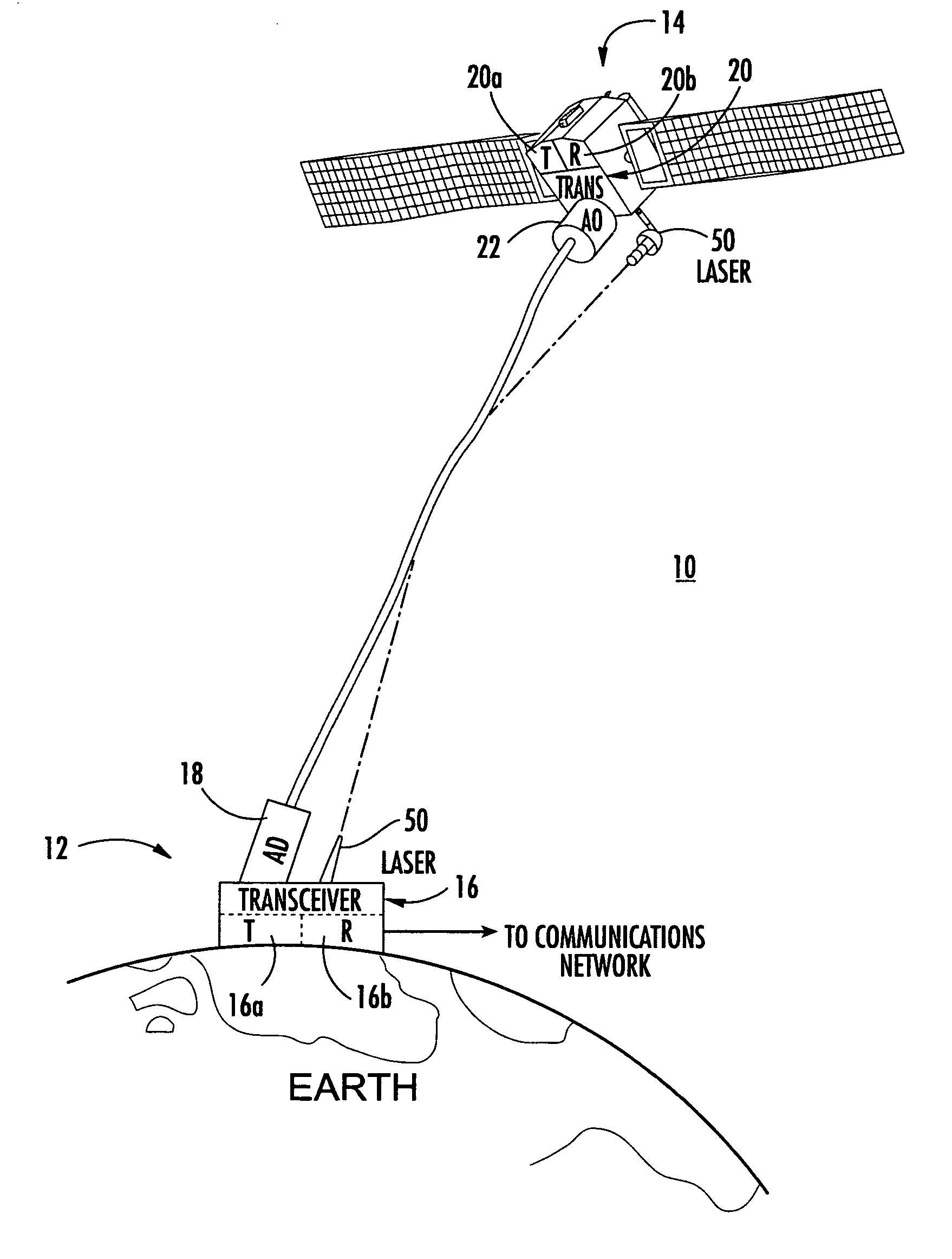
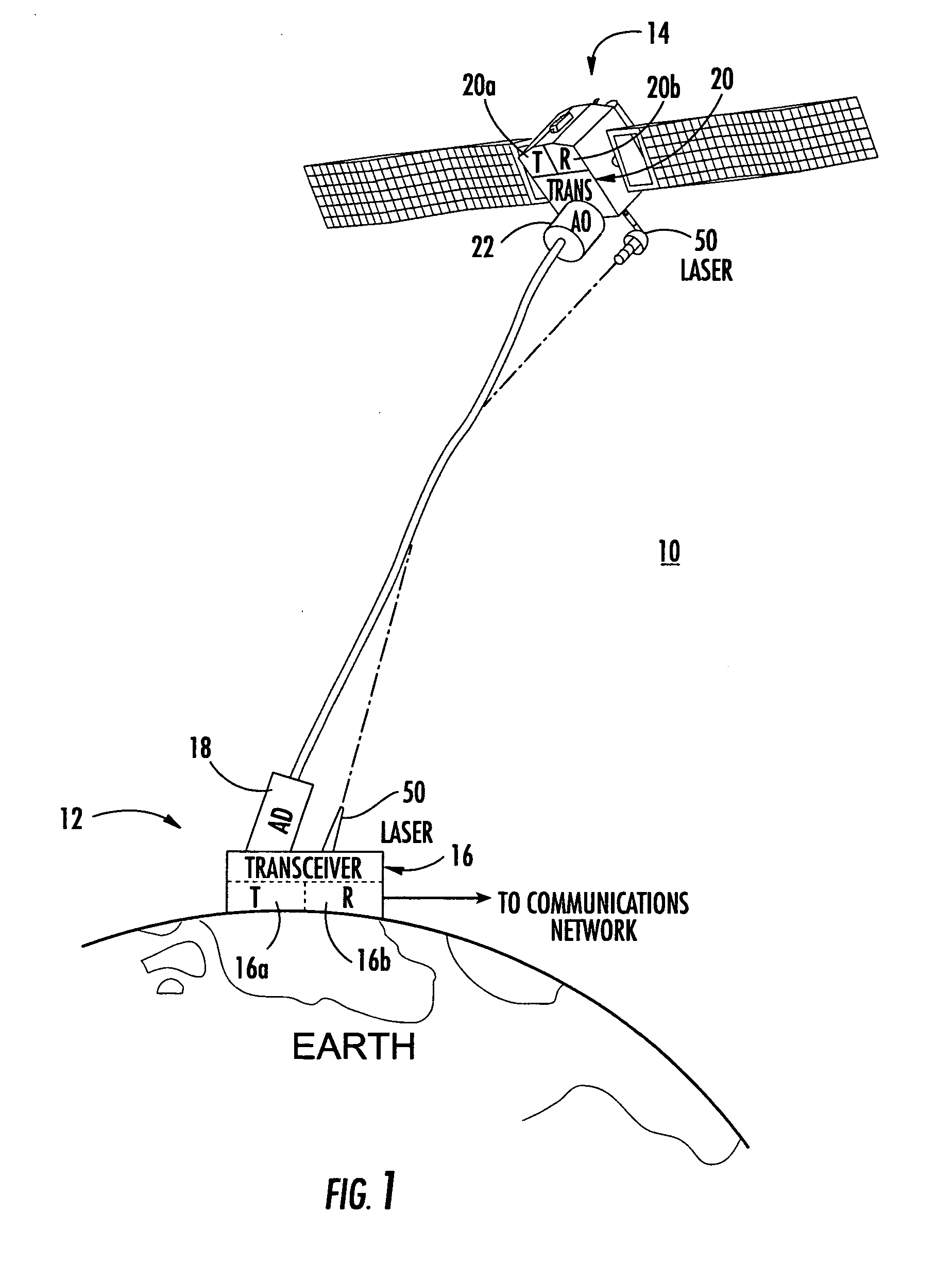
[0021] The present invention overcomes the disadvantages of prior art proposals for free-space optical communication systems between a ground station and satellite. The present invention does not require a satellite to carry on-board large optics, very high power optical transmitters and their associated power supplies. Furthermore, the present invention greatly reduces t...


PUM


Abstract

A system and method of free-space optical satellite communications includes a ground station and transceiver for transmitting and receiving an optical communications signal. Adaptive optics at the ground station are operative with the transceiver for determining the shape of any distortions in the wavefront of the optical communications signal and compensating at the ground station for the distortions. A satellite includes a transceiver for transmitting and receiving the optical communications signal and includes adaptive optics for determining the shape of any distortions in the waveform of the optical communications signal and compensating at the satellite for the distortions.

Description

FIELD OF THE INVENTION [0001] This invention relates to optical communications, and more particularly, this invention relates to free-space optical communications. BACKGROUND OF THE INVENTION [0002] Optical communication systems between ground stations and earth orbiting satellites have not been practiced because of the distortion impacts imposed by the atmosphere on the optical beam forming the optical communications signal. Temperature fluctuations, aerosols, water vapor, and air density changes cause changes in the index of refraction to create a multitude of small lenses that refract the light many times by small amounts. Furthermore, suspended particulate matter creates multiple diffractions of the optical beam. When the optical communications signal reaches the optics located on an earth orbiting satellite or ground receiving station, the wavefront of the optical communications signal can be badly distorted in both magnitude and phase. As a result, the optical communications s...

Claims


Application Information

Patent Timeline
Patent Type & Authority Applications(United States)
IPC IPC(8): H04B10/118
CPCH04B10/118
Inventor TEGGE, EDWARD H. JR.
Owner HARRIS CORP
Why Eureka
Try Eureka