

Laminate for IR ablation
- Summary
- Abstract
- Description
- Claims
- Application Information
AI Technical Summary
Benefits of technology
Problems solved by technology
Method used
Image

Examples
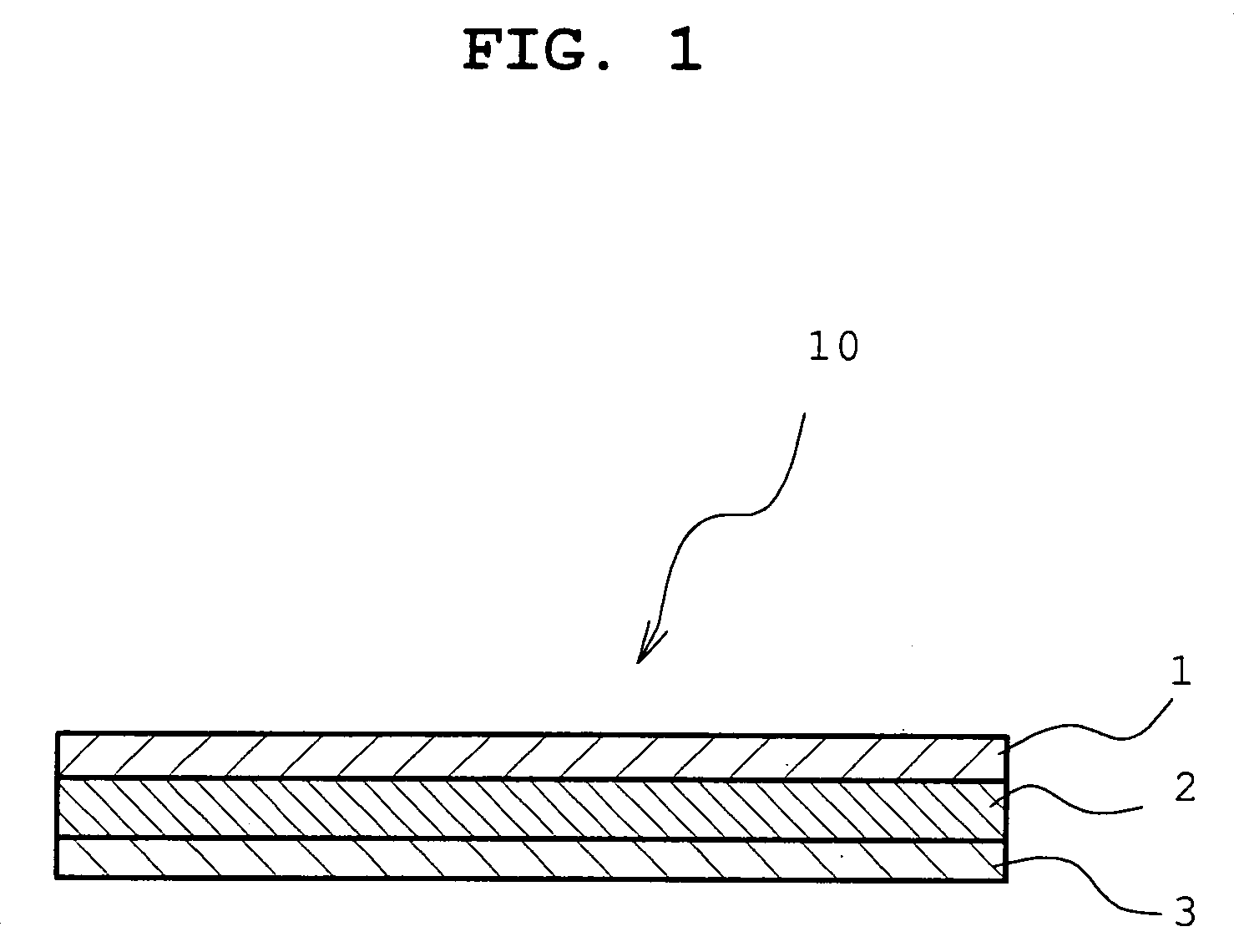
example 1
Preparation of Laminate for IR Ablation
[0077] An aqueous solution of polyvinyl alcohol (GOHSENOL AH-26 manufactured by NIPPON SYNTHETIC CHEMICAL INDUSTRY CO., LTD.) / propylene glycol (manufactured by ASAHI DENKA Co., Ltd.) / surfactant (EPAN 740 manufactured by Dai-ichi Kogyo Seiyaku Co., Ltd.,) / pure water=8.75 g / 8.75 g / 0.01 g / 332.5 g was applied to a PET film (substrate (cover film), whole cloth was manufactured by Toyo Boseki Kabushiki Kaisha, E5002, thickness 125 μm), that had undergone a chemical matte treatment with a barcoater #26, and dried at 100° C. for 3 min to form a film having a thickness after drying of 1 μm (IR non-sensitive polymer resin layer). Then, aluminum was evaporated on the surface of the film by vacuum deposition process in a thickness of about 800 Å to form an IR abrasion layer (IR absorbent metal layer), whereby a laminate for IR abrasion (aluminum deposited film) was obtained. The optical density of the IR abrasion layer was 3.5. The optical density (OD) i...
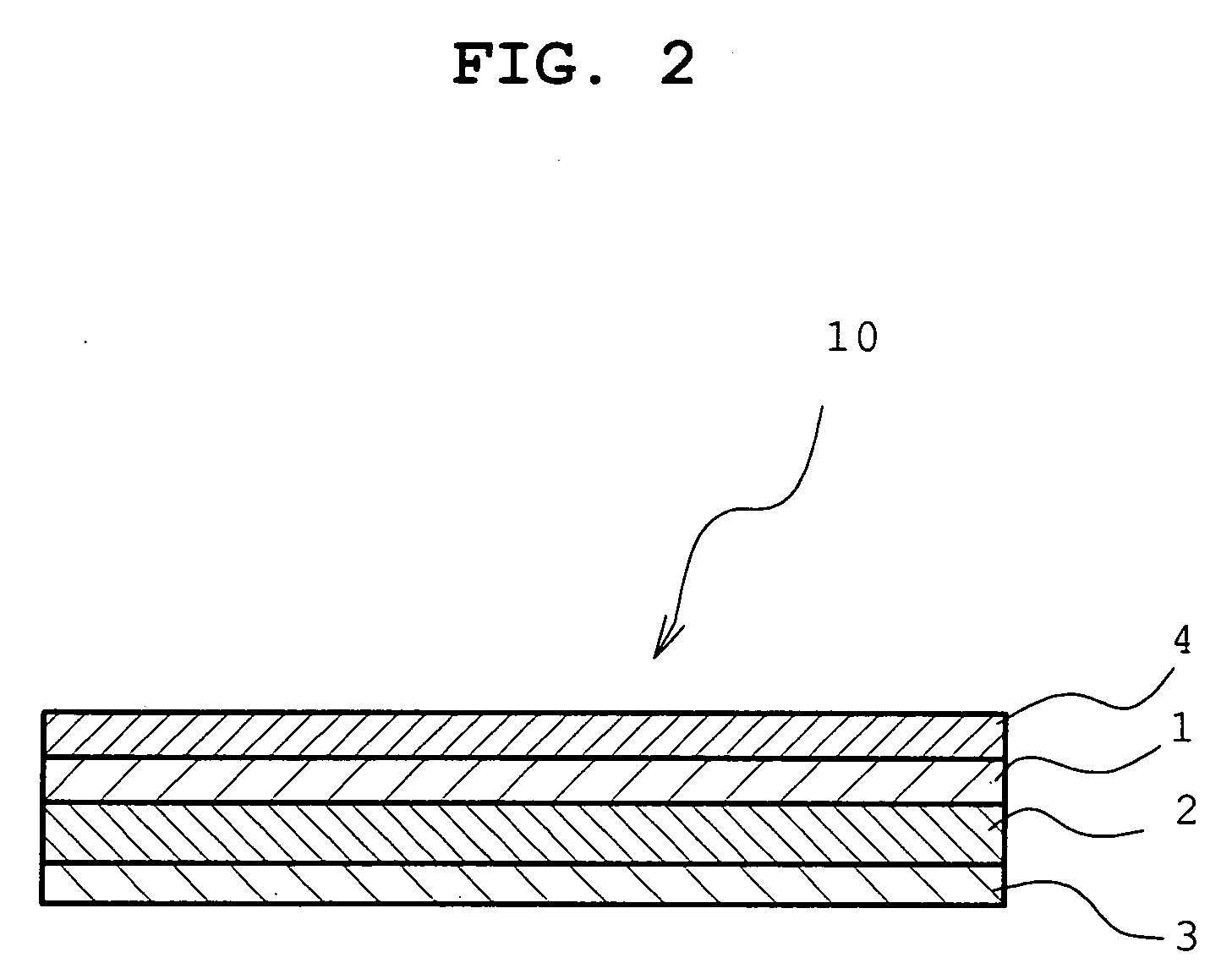
example 2
Preparation of Laminate for IR Ablation Having Anti-Blocking Layer
Production of Alkyd Resin Modified with Saturated Fatty Acid
[0078] Phthalic anhydride and glycerol were heated to 180° C. to give a first stage syrup. Molten stearic acid was added to esterify a free hydroxyl group. Heating was continued from 180° C. to 220° C. to allow reaction to reach an acid value of 10 (KOH mg / g) to give a stearic acid-modified alkyd resin.
Production of Anti-Blocking Layer
[0079] The obtained stearic acid-modified alkyd resin (400 parts) and a methylated melamine resin (100 parts, Sumitomo Chemical Co., Ltd: SUMIMAL M-100) were dissolved in toluene (25000 parts) and methyl ethyl ketone (24500 parts) to give a coating solution having a solid content of 1 wt %. The coating solution was applied to one surface of a biaxially stretched polyethylene terephthalate film (substrate (cover film), E5002 manufactured by Toyo Boseki Kabushiki Kaisha) having a thickness of 100 μm, a width of 1000 mm and ...
example 3
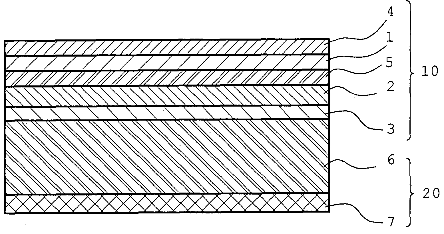
Preparation of Laminate for IR Ablation Having Release Layer
Production of Release Layer
[0081] Stearic acid-modified alkyd resin. (400 parts) obtained in Example 2 and methylated melamine resin (100 parts, Sumitomo Chemical Co., Ltd.: SUMIMAL M-100) were dissolved in toluene (25000 parts) and methyl ethyl ketone (24500 parts) to give a coating solution having a solid content of 1 wt %. The coating solution was applied to one surface of a biaxially stretched polyethylene terephthalate film (substrate (cover film), E5002 manufactured by Toyo Boseki Kabushiki Kaisha) having a thickness of 100 μm, a width of 1000 mm and a length of 1200 m by gravure coating to give a roll of film having a coating of a release layer. The thickness of the release layer after coating and drying was 0.1 μm.
Production of IR Ablation Layer
[0082] A coating solution having a solid content of 5 wt %, which had been prepared by dissolving polyvinyl alcohol (2000 parts, GOHSENOL KH-20 manufactured by NIPPON ...
PUM
| Property | Measurement | Unit |
|---|---|---|
| Thermosetting | aaaaa | aaaaa |
| Sensitivity | aaaaa | aaaaa |
| Photosensitivity | aaaaa | aaaaa |
Abstract
Description
Claims
Application Information