Acceleration sensor system

a sensor system and acceleration technology, applied in the field of acceleration sensor systems, can solve the problems of difficult module combination, disadvantageous offset stability of output voltage and sensitivity, and large manufacturing tolerance of various samples, so as to achieve good measuring properties, low production expenditure, and low cost

Inactive Publication Date: 2005-05-19
ROBERT BOSCH GMBH
View PDF4 Cites 13 Cited by
  • Summary
  • Abstract
  • Description
  • Claims
  • Application Information

AI Technical Summary

Benefits of technology

[0004] By comparison, the acceleration sensor system according to the present invention particularly has the advantage that a sensor system having good measuring properties is achievable, using low production expenditure and advantageously low costs. In this connection, especially good electrical characteristic data, which correspond to those of known ceramic-hybrid constructions may be achieved, together with a good assembling capability on printed circuit boards in standard assembly processes (SMD). Consequently, for example, the sensors in control units and separately built sensors may be combined on one printed circuit board.
[0005] The sensor system according to the present invention is also adaptable to the respective requirements for the electrical sensor characteristic quantities and environmental influences. In this connection, as a function of the requirements, a requisite electrical performance and robustness with respect to environmental influences may be achieved in that, based on the flexible construction within the premold housing, components may be added in order to respond to higher requirements or components may be omitted appropriately for cost reduction.
[0006] A surprisingly good stress decoupling is achieved by using an adhesive layer having a uniform thickness greater than 50 μm, preferably greater than 100 μm, a soft adhesive material being used which is, in particular, softer than the chip

Problems solved by technology

However, such modules are generally not easy to combine using joining techniques suitable for mass production, such as printed circuit board assembly and press-in methods.
In sensors produced by microstructuring and integrated electronic circuits, because of different coefficients of expansion of the plastic and the semiconductor material of the sensors and the circuits, as well as on account of relaxation phenomena in the plastic, this leads t

Method used


Image

  • Acceleration sensor system
  • Acceleration sensor system

Examples


Embodiment Construction

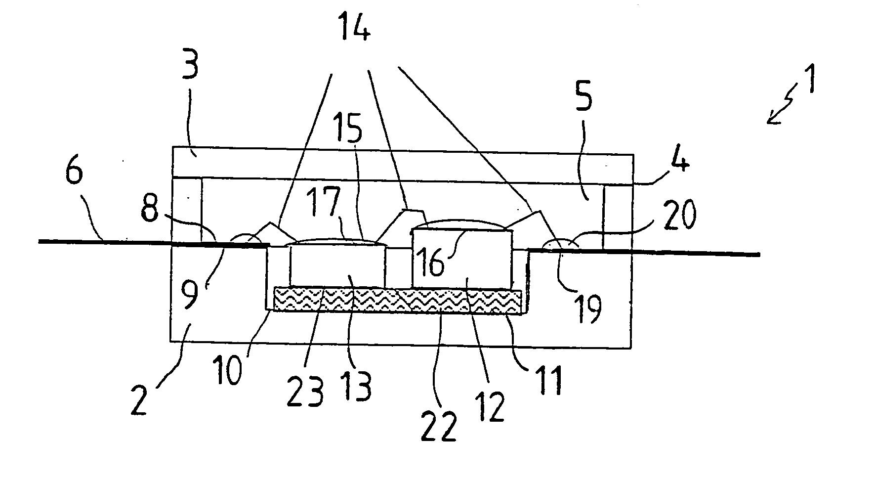
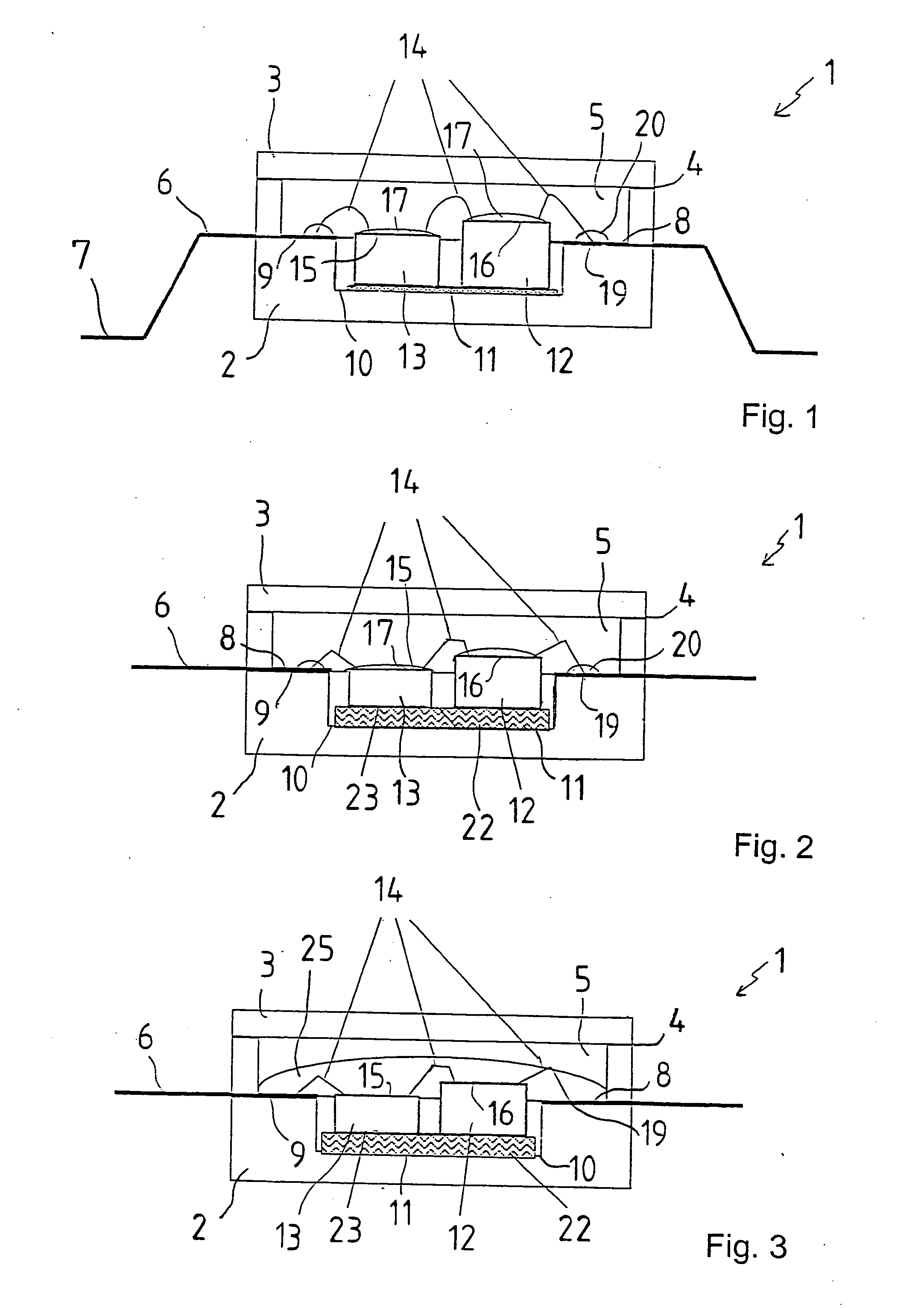
[0017] A sensor system 1 has a premold housing 2, 3 having housing lower part 2 and cover 3, which are bonded to each other in a connecting region 4, for instance, by laser welding or by adhesion, and which surround a housing inner chamber 5.

[0018] According to FIG. 1, a lead frame 6 runs through housing lower part 2 and may be set onto a printed circuit board (that is not shown) using its terminal pins 7. In the housing inner chamber 5, middle regions 8 of lead frame 6 run on a stage 9 of housing lower part 2. On a floor area 10 below stage 9, an adhesion layer 11 has been applied onto which a sensor chip 12 and an evaluation ship 13, e.g. an ASIC (application-specified integrated circuit) are applied. Adhesive layer 11 is advantageously formed by a soft adhesive, which in particular is softer than the material of sensor chip 12, and has a specified layer thickness. In this case, adhesive layer 11 may have a uniform thickness greater than 50 μm, advantageously greater than 100 μm,...


PUM


Abstract

An acceleration sensor system is especially suitable for measuring low accelerations. The acceleration sensor system has at least: one premold housing made of a plastic material having a housing inner chamber, one lead frame which extends through the premold housing in the housing inner chamber, and one acceleration sensor chip, which is fastened in the housing inner chamber with the aid of an adhesive layer, and is connected to the lead frame with the aid of line bond connections. Advantageous stress decouplings are achieved in this connection by using an adhesive layer having a uniform thickness greater than 50 μm, preferably greater than 100 μm, in particular, the adhesive material of the adhesive layer being softer than the chip material of the acceleration sensor chip.

Description

FIELD OF THE INVENTION [0001] The present invention relates to an acceleration sensor system, which is able to be used especially for measuring accelerations having tight tolerances of the sensor parameters with respect to temperature and service life. BACKGROUND INFORMATION [0002] Acceleration sensor systems for low accelerations (low G acceleration sensors), which are used, for example, for measuring a braking deceleration or a slope inclination of a motor vehicle, are generally constructed in hybrid technology using hermetically sealed housings, in order to minimize environmental and temperature influences. However, such modules are generally not easy to combine using joining techniques suitable for mass production, such as printed circuit board assembly and press-in methods. [0003] Such sensor systems have great sensitivity with regard to mechanical strains, since the sensor signals are generally read out capacitatively, and evaluated at high amplification. In cost-effective, pr...

Claims


Application Information

Patent Timeline
IPC IPC(8): B81B7/00G01P1/02G01P15/125
CPCB81B7/0048G01P15/125G01P1/023B81B2201/0264H01L2224/48137H01L2224/48247H01L2224/73265H01L2224/8592H01L2924/16195
Inventor EMMERICH, HARALDBEUTEL, HANSJOERG
Owner ROBERT BOSCH GMBH
Why Eureka
Try Eureka