
High-powder tungsten-based sintered alloy

a technology of tungsten-based alloys and high-powder, which is applied in the direction of ammunition projectiles, transportation and packaging, weapons, etc., can solve the problems of fine porosities and the small market share of tungsten-based alloys

Inactive Publication Date: 2005-05-19
CIME BOCUZE SA
View PDF12 Cites 6 Cited by
  • Summary
  • Abstract
  • Description
  • Claims
  • Application Information

AI Technical Summary

Benefits of technology

[0020] The aim of the invention is thus to propose a sintered material and a preparation process implementing high power sintering conditions allowing tungsten-based alloys to be sintered in a short time and a fully densified material, such as that obtained at the end of a conventional sintering operation by thermal radiation, to be produced.
[0021] A further aim of the present invention is to additionally obtain, using specific heating powers, tungsten-based alloys, which at the end of the sintering cycle has low grain-sized microstructures and very low contiguity between the tungsten crystals.
[0024] and a dispersion of micro-oxides with no loss of ductility properties.
[0034] Remarkably, with alloys from W—Ni—Fe—Co and W—Ni—Co systems, the invention leads to materials whose mechanical properties provide a resistance-ductility trade-off that is better than that obtained using conventional sintering conditions.
[0039] enable two-phased tungsten-based alloys to be prepared by sintering in a neutral, non reducing, gas, such as nitrogen or argon, leading to a dispersion of micro-oxides with no loss of ductility,

Problems solved by technology

We note that, if this process allows a homogeneous structure to be obtained, it nevertheless leads to the presence of fine porosities.
Furthermore, these processes have never been applied to tungsten-based alloys with a preparation in the liquid phase since the expert was more inclined to think that this process gave results that were at best only equivalent to those obtained by classical processes.
Moreover, tungsten-based alloys only represent a very small share of the tungsten market despite their producing very interesting performances.

Method used


Image

  • High-powder tungsten-based sintered alloy
  • High-powder tungsten-based sintered alloy
  • High-powder tungsten-based sintered alloy

Examples


example 1

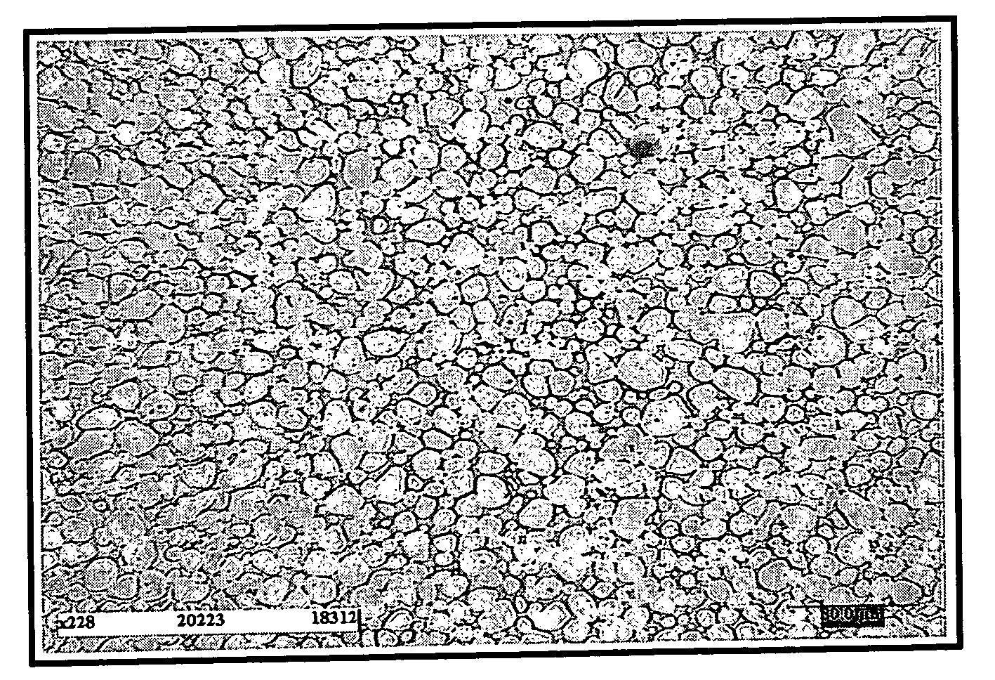
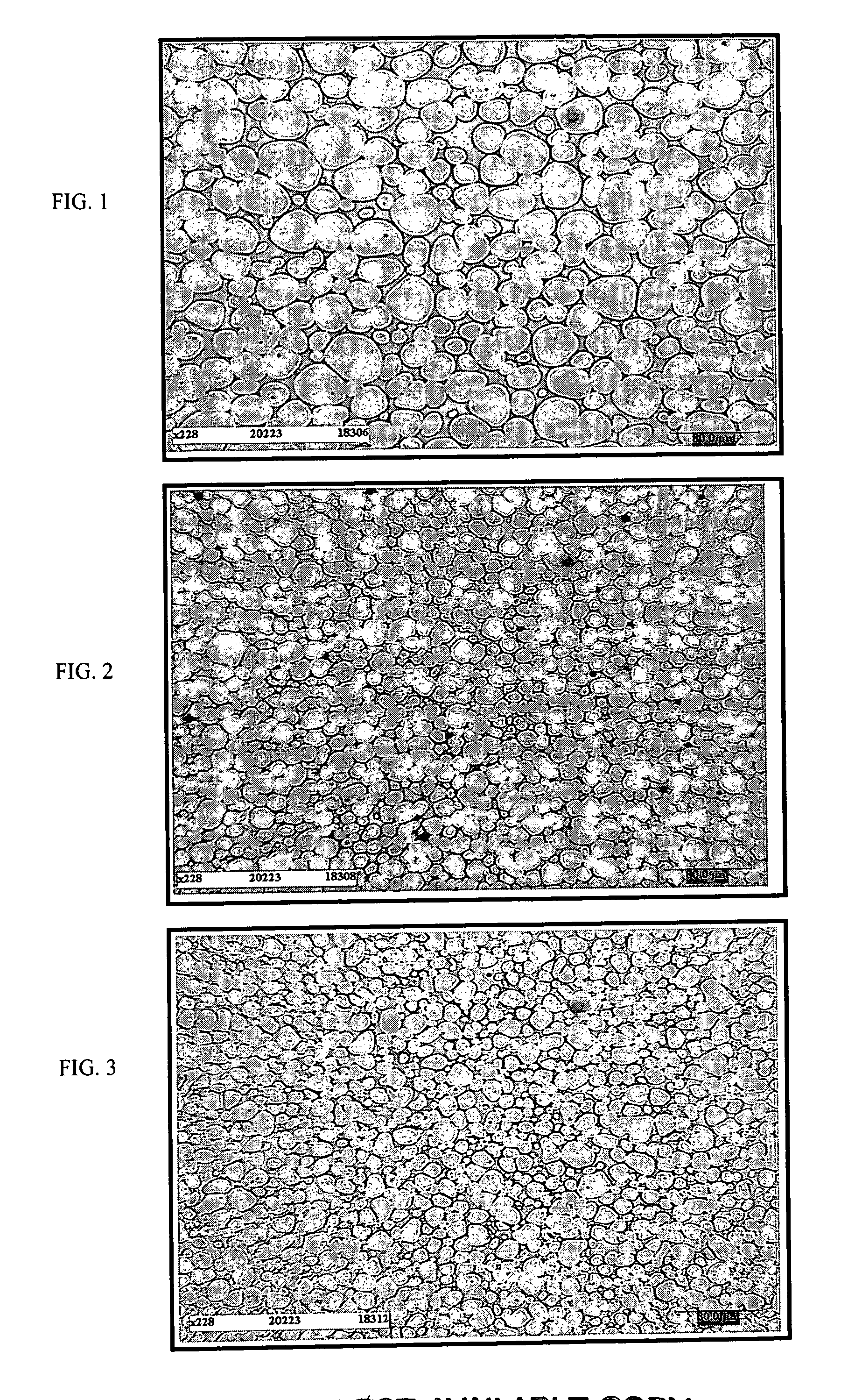
[0058] A bar is prepared from a W—Ni—Fe—Co alloy having the following composition in mass: tungsten 93%, nickel 4.05%, iron 1% and cobalt 1.95% which is then subjected to the sintering operation according to the invention: [0059] density 17.6 [0060] geometry: cylinder Ø 10, L=90 mm, [0061] compression: 2.108 Pa [0062] sintering by induction in N2, [0063] time to reach T max 1500° C.: [0064] temperature build-up rate: δT / δt˜300° C. / mn, [0065] time at 1500° C. stage: 3 mn (sintering time at liquid phase:

[0066] The following characteristics are obtained: [0067] relative density: 100% (theoretical d: 17.79) [0068] porosity: none

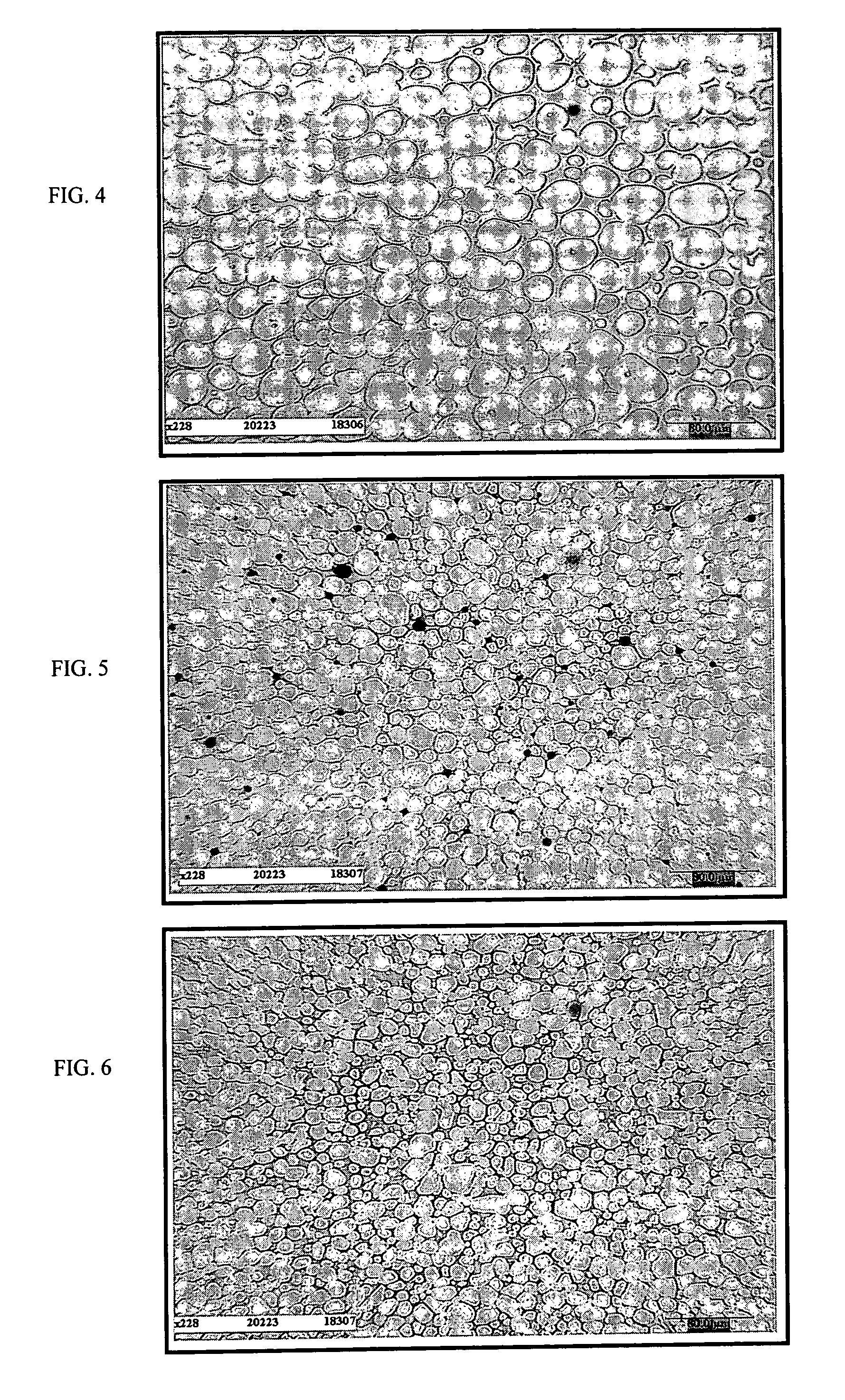
[0069] On a microstructural level, we observe: [0070] In FIG. 1, we see a bar having the same composition but sintered according to prior art which has the following characteristics: Vα=84.8%, Lα=20.1 μm, Cαα(%)=22.3%, λγ=3.6 μm. [0071] In FIG. 2, which shows the micrograph of the material without any previous reduction processing, the material according to the...

example 2

[0075] A bar is prepared from a W—Ni—Fe—Co alloy (91, 6.2, 0.3, 2.5%) having a density of 17.1 by processing in the liquid phase according to the invention as explained previously: [0076] geometry: cylinder ø 10, L=90, [0077] compression: 2.108 Pa [0078] sintering by induction in N2 in the liquid phase, [0079] time to reach T max 1500° C.: [0080] temperature build-up rate: δT / δt˜400° C. / mn, [0081] time at 1500° C. stage: 3 mn (sintering time at liquid phase:

[0082] The following results are obtained: [0083] relative density: 100% (theoretical d: 17.45) [0084] porosity: none

[0085] On a microstructural level, we observe: [0086] In FIG. 4, we see a bar having the same composition but sintered according to prior art which has the following characteristics: Vα=80.2%, Lα=20.0 μm, Cαα(%)=15%, λγ=4.9 μm. [0087] In FIG. 5, which shows the micrograph of the material without any previous reduction processing, the material according to the invention and according to example 2 has the following...

example 3

[0091] A bar is prepared from a W—Ni—Co alloy (91, 6, 3%) having a density of 17.5 by processing in the liquid phase according to the invention as explained previously: [0092] geometry: cylinder ø 10, L=90, [0093] compression: 2.108 Pa [0094] sintering by induction in N2, [0095] time to reach T max 1500° C.: [0096] temperature build-up rate: δT / δt˜300° C. / mn, [0097] time at 1530° C. stage: 3 mn (sintering time at liquid phase: [0098] relative density: 100% (theoretical d: 17.45) [0099] porosity: none

[0100] On a microstructural level, we observe: [0101] In FIG. 7, we see a bar having the same composition but sintered according to prior art which has the following characteristics: Vα=78%, Lα=19 μm, Cαα(%)=17.8%, λγ=5.4 μm. [0102] In FIG. 8, which shows the micrograph of the material without any previous reduction processing, the material according to the invention and according to example 3 has the following characteristics: Vα=76.7%, Lα=8.2 μm, Cαα(%)=11.3%, λγ=2.5 μm. [0103] In FIG...


PUM

PropertyMeasurementUnit
Temperatureaaaaaaaaaa

Abstract

Tungsten-based alloy material sintered at a high sintering power that may contain additive elements soluble in the nickel and selected from the group constituted, for example, by rhenium, molybdenum, tantalum, niobium, vanadium or a mixture of these, wherein, after sintering in liquid phase at a temperature of around 1500° C., it has: a two-phased α-γ microstructure that is fully densified, has no porosities or has negligible porosities of a low mean grain size (Lα) and a contiguity (Cαα) that is very low with respect to the size of the tungsten crystals, and a dispersion of micro-oxides with no loss of ductility properties.

Description

BACKGROUND OF THE INVENTION [0001] The technical scope of the present invention is that of tungsten-based alloy sintered materials. [0002] By tungsten-based alloys we mean alloys mainly enclosing tungsten associated with nickel, iron and cobalt, or nickel and manganese, or nickel and chromium, or nickel and iron and including such additive elements as rhenium, molybdenum, niobium, vanadium, tantalum, or a mixture of these. [0003] The usual manufacturing process for a sintered material from alloys based on W—Ni (Fe, Co, Cr, Cu, Mn), that may contain other additive elements such as rhenium or molybdenum, more often than not consists in sintering, in the liquid phase, in through-type furnaces or static furnaces, with heating by radiation, for a processing time of several hours. Alloys based on systems such as W—Ni—Fe—Co, W—Ni—Co, W—Ni—Cu, W—Ni—Cr or W—Ni—Mn are thus industrially prepared in this manner. [0004] In a known manner, sintering cycles incorporate three main stages: [0005] a ...

Claims


Application Information

Patent Timeline
IPC IPC(8): C22C1/04C22C27/04F42B12/74
CPCB22F2998/10B22F2999/00C22C1/045C22C27/04F42B12/74B22F1/0003B22F1/0088B22F3/02B22F3/1035B22F2201/013B22F1/145B22F1/09
Inventor MAHOT, PASCALNICOLAS, GUYVOLTZ, MARC
Owner CIME BOCUZE SA
Learn More