Electromagnetic device, high-voltage generating device, and method for making the electromagnetic device

a high-voltage generating device and electromagnetic technology, applied in the direction of magnets, fixed transformers, magnetic bodies, etc., can solve the problems of affecting the quality of the electromagnetic device, the coating of the coil winding to be peeled off, and the terminal connection with the coil winding may be secured with much difficulty, so as to achieve the effect of cost reduction

Inactive Publication Date: 2005-05-19
MATSUSHITA ELECTRIC WORKS LTD
View PDF5 Cites 6 Cited by
  • Summary
  • Abstract
  • Description
  • Claims
  • Application Information

AI Technical Summary

Benefits of technology

[0014] In the present invention, an electromagnetic device comprises a magnetic core having a curved side and a flat rectangular wire conductor wound in an edge-wise winding form directly on the curved side of the magnetic core. Accordingly, as any insulator such as a coil bobbin is not needed between the flat rectangular wire conductor and the magnetic core, the winding can be decreased in the overall size or thickness, thus contributing to the dimensional reduction and the improvement of characteristics of the device. In the device, the magnetic core has an intrinsic resistance of not smaller than 1000 Ω.m.
[0015] The electromagnetic device further comprises a winding provided on the outer surface of the flat rectangular wire conductor. Accordingly, a resultant transformer can be reduced in the thickness.
[0016] The magnetic core is rough finished at the surface. Accordingly, as no extra step such as polishing is needed after the completion of the magnetic core, the production cost of the magnetic core can be lowered. Also, the flat rectangular wire conductor can be protected from slipping and tilting down during the edge-wise winding process.

Problems solved by technology

In case of a bobbin-less device, the terminals connected with the coil windings may be secured with much difficulty.
Since the coil windings of a metallic material create undesired events of spring back, their ends have to be bound together or supported by any proper means.
The edge-wise winding may cause the coating of the coil windings to be peeled off when its curvature radius is too small.

Method used


Image

  • Electromagnetic device, high-voltage generating device, and method for making the electromagnetic device
  • Electromagnetic device, high-voltage generating device, and method for making the electromagnetic device
  • Electromagnetic device, high-voltage generating device, and method for making the electromagnetic device

Examples


embodiment 1

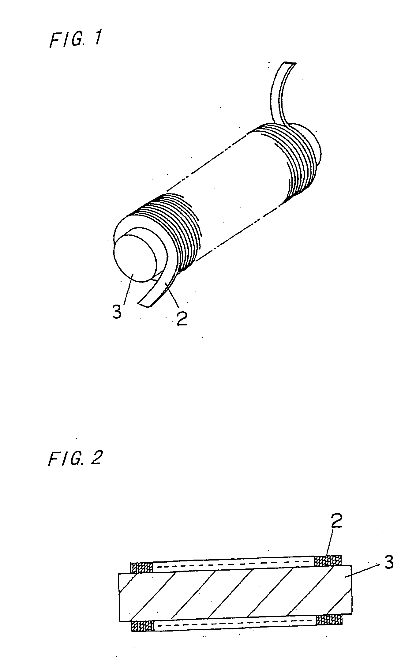
[0046] An electromagnetic device of this embodiment is a single-winding inductor having a winding wound directly on a rod magnetic core 3 arranged of substantially a cylindrical shape with no need of an insulator such as a coil bobbin as-shown in FIGS. 1 and 2.

[0047] The magnetic core 3 is made of an Ni—Zn ferrite material which is high in the resistivity (intrinsic resistance) and about 8 mm in the diameter of its cylindrical shape. The winding is a flat rectangular wire conductor 2 (for example, having a thickness of 70 μm and a width of 1.4 mm) wound in a single layer of edge-wise winding form on substantially the entire length of the magnetic core 3. More specifically, the flat rectangular wire conductor 2 is wound on the magnetic core 3 which is secured at both axial ends to jigs and then rotated by a rotating motion of the jigs.

[0048] It is found from examination of the insulation coating (not show) of the flat rectangular wire, conductor 2 wound on the magnetic core 3 in th...

embodiment 2

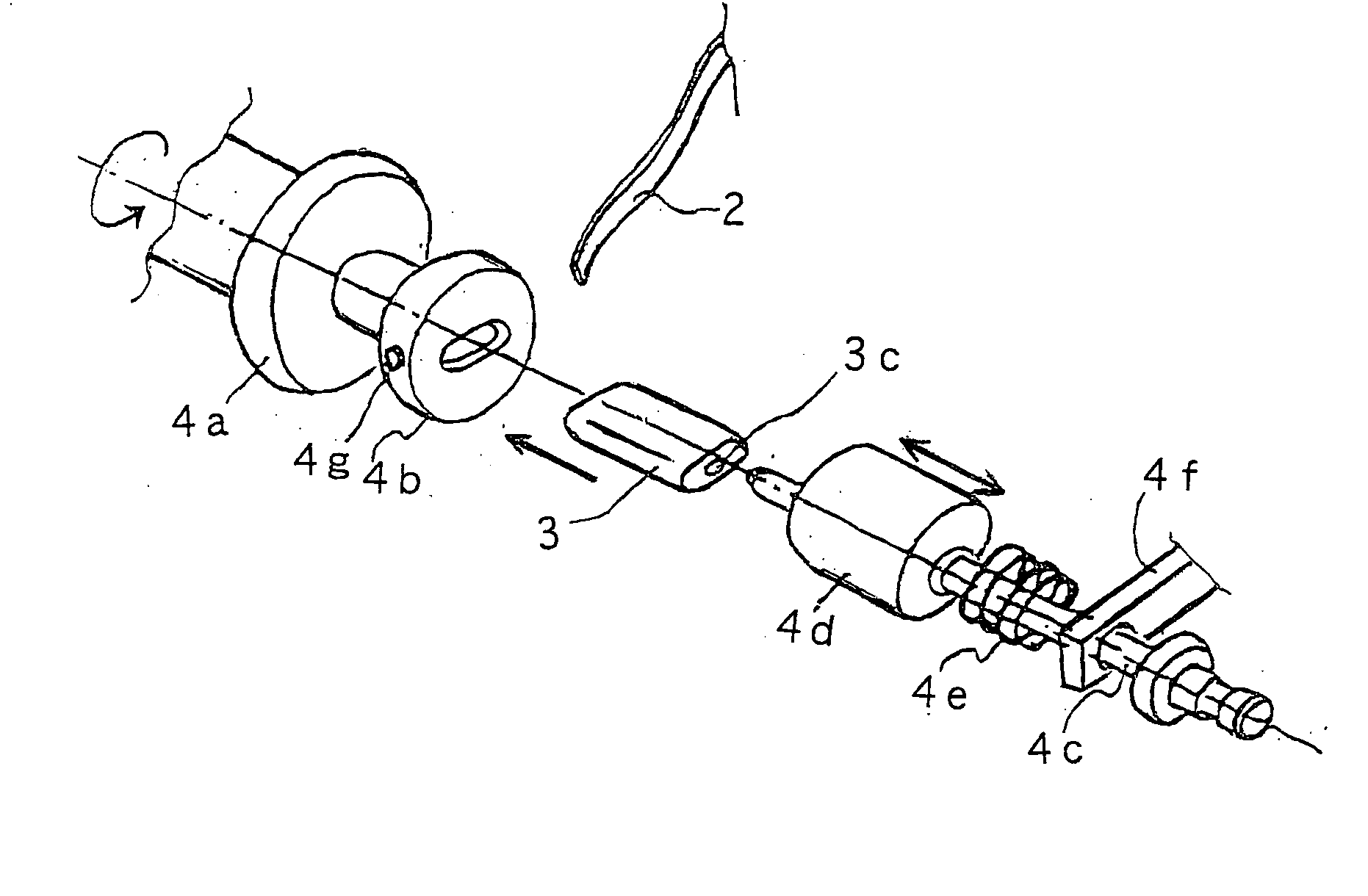
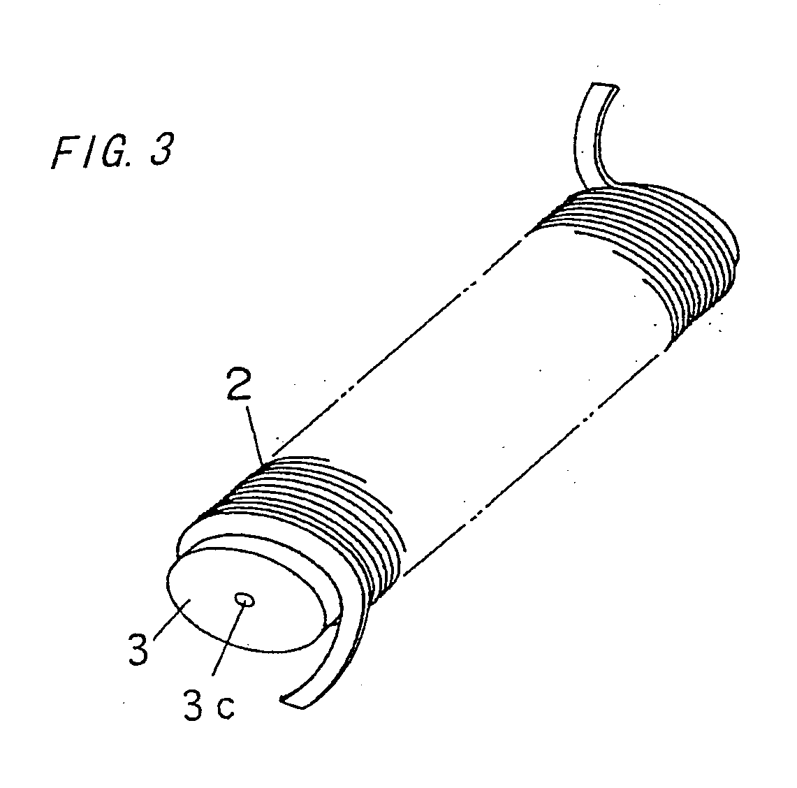
[0050] This embodiment is characterized by a magnetic core 3 having an elliptical shape in the cross section as shown in FIG. 3. As the other arrangement is identical to that of Embodiment 1, like components are denoted by like numerals and will be described in no more detail (throughout the embodiments and their drawings).

[0051] The magnetic core 3 is made of an Ni—Zn ferrite material identical to that of Embodiment 1 but having an elliptical shape in the cross section on which a flat rectangular wire conductor 2 is directly wound in an edge-wise winding form. As its magnetic core 3 has an elliptical shape in the cross section, the inductor can be lower in the height than that of Embodiment 1.

[0052] The magnetic core 3 has a hemispheric recess (pit) 3c of about 2 mm in diameter provided at the center in each end thereof. While the flat rectangular wire conductor 2 is being wound on the magnetic core 3 by the action of a winder 4, the magnetic core 3 is secured to the winder with ...

embodiment 3

[0057] This embodiment is characterized by, a magnetic core 3 having a through hole 3d provided along the axial direction therein as shown in FIG. 5. The magnetic core 3 like that of Embodiment 2 is arranged of an elliptical shape in the cross section and its through hole 3d, of about 2 mm in the diameter extends along the axial direction between two ends thereof. This allows the magnetic core 3 to be securely held by a jig inserting into the through hole 3d for ease of the winding of the flat rectangular wire conductor 2. In addition, the magnetic core 3 can tightly be secured to a housing 7 of the winder with its through hole 3d accepting and engaging with a bar-like projection 7a extending from the housing 7, as shown in FIG. 6. The projection 7a may be implemented by a retaining screw. The magnetic core 3 may be arranged of a cylindrical shape similar to that of Embodiment 1.


PUM

PropertyMeasurementUnit
intrinsic resistanceaaaaaaaaaa
diameteraaaaaaaaaa
widthaaaaaaaaaa

Abstract

An electromagnetic device and a high-voltage generating device which are thin and improved in the characteristics are provided in which a magnetic core 3 is made of a cylindrical form of a ferrite material having a higher intrinsic resistance. A winding is provided by winding a flat rectangular wire conductor 2 in an edge-wise winding form directly on substantially the entire length of the magnetic core 3. As any insulator such as a coil bobbin is not needed between the flat rectangular wire conductor 2 and the magnetic core 3, the winding can be decreased in the overall size or thickness thus contributing to the dimensional reduction of the electromagnetic device. Also, as its flat rectangular wire conductor 2 is wound directly on the magnetic core 3, the winding can be minimized in the length and thus the overall resistance. Moreover, as there is no gap between the winding and the magnetic core 3, the self-inductance can be reduced while the size and the number of turns of the winding remain unchanged.

Description

[0001] This application is a continuation of Application Ser. No. 09 / 129,105, filed Jul. 7, 2002, the contents of which are expressly incorporated by reference herein in its entireties.FIELD OF THE INVENTION [0002] The present invention relates to an electromagnetic device, a high-voltage generating device, and a method for making the electromagnetic device. BACKGROUND OF THE INVENTION [0003] It is necessary for starting a high intensity discharge lamp such as a high-intensity discharge (HID) lamp to use a high-voltage generating device called an igniter. The high-voltage generating device is generally provided in the form of ant electromagnetic device such as a pulse transformer for converting a low-voltage input to a high-voltage output of pulsed waveform (as disclosed in, for example, Japanese Patent Laid-open Publications 11-16752 and 11-74132). [0004] One of such conventional electromagnetic devices is shown in structure in FIGS. 65 to 68. A coil bobbin 60 is made of an insulat...

Claims


Application Information

Patent Timeline
Patent Type & Authority Applications(United States)
IPC IPC(8): C12N15/10C12Q1/68H01F17/04H01F27/28H01F30/06H01F38/10H01F41/06H05B41/04
CPCC12N15/101C12Q1/6827H01F17/045H01F27/2823H01F30/06H01F38/10Y10T29/49071H01F2017/046H05B41/042H01F41/0633C12Q2565/137C12Q2527/107H01F41/082
Inventor KAKEHASHI, HIDENORIKANBARA, TAKASHIFUJIWARA, TORUTAKAMATSU, KENICHINAKANO, TOMOYUKIKINUTANI, KAZUHIKOCHUZAWA, TAKAAKISATOU, MASAKIMIYAI, TAKAO
Owner MATSUSHITA ELECTRIC WORKS LTD
Why Eureka
Try Eureka