
Liquid discharge head and method of manufacturing thereof, and method of manufacturing piezoelectric element

Inactive Publication Date: 2005-05-19
CANON KK
View PDF4 Cites 12 Cited by
  • Summary
  • Abstract
  • Description
  • Claims
  • Application Information

AI Technical Summary

Benefits of technology

[0019] The present invention is devised in view of the problems which are inherent to the above-mentioned technology and which has not yet been solved. In a typical embodiment of the present invention, a specified glass material having an excellent characteristic so as to be used as a diaphragm, and having a high heat resistance and a linear expansion coefficient which is nearly equal to that of an Si substrate, is anodically joined to the Si substrate (flow passage substrate) which has been finely processed beforehand, then the glass diaphragm is thinned by polishing so as to have a thickness not greater than 10 μm so as to have a slight flexion in a pressure generation chamber, and thereafter electrode layers and a piezoelectric film are directly deposited on the thinned glass diaphragm, thereby it is possible to prevent occurrence of deformation and peel-of of the piezoelectric film caused by thermal strain of the glass diaphragm during deposition and crystallization of the piezoelectric film. Thus, an object of the present invention is to provide a liquid discharge head which can greatly contribute to the enhancement of the reliability of the discharge performance and the cost reduction of a liquid discharge type recording apparatuses or the like, and is to provide also a method manufacturing thereof.

Problems solved by technology

Thus, it is relatively disadvantageous to use these materials for the additional substrate which is consumed away by one time of film deposition.
In addition, in the case of deposition of a piezoelectric film on a single crystal substrate, since only the single crystal substrate should be removed by melting with hot phsphric acid or the like after it is bonded to a glass substrate serving as a diaphragm, and since this melting requires a very long time, it is extremely disadvantageous in view of not only the costs but also the throughput thereof, resulting in build-up of a great barrier against the mass-production thereof.
However, the linear expansion coefficient of SiN is extremely small in comparison with that of Si, and accordingly, the PZT film is susceptible to peel off from the Si substrate during a heat-treatment process, that is, it is disadvantages in view its process.
In this case, a loss is possibly caused during bonding between the finely processed articles, and accordingly, there would be caused a risk of lowering the yield thereof.
That is, it is difficult to enhance the yield since the Si substrate cannot be processed beforehand.
Thus, there is a risk of lowering the joint strength during the heat treatment, and further, it is difficult to completely crystallize the PZT base at a temperature of 500° C.
Further, it cannot be assured to prevent the joint part of the diaphragm by anodic joint from peeling off at a high temperature up to 1,000° C.
In such a manufacturing method, when the PZT film is cooled after it is crystallized at a high temperature, the lattice constant thereof is greatly changed being affected by a thermal expansion coefficient of the Si substrate serving as a film deposition substrate, and accordingly, the piezoelectricity of the PZT film is greatly deteriorated.
Thus, it may be considered that the piezoelectricity is possibly deteriorated by a large degree.
However, in this method, the 90 deg. domain which does not contribute to the piezoelectricity of the PZT film, tends to contrarily increase, and accordingly, the piezoelectricity is remarkably deteriorated.
Accordingly, Since the lengths with which the films make contact with each other are equal to each other among the areas, the film thickness is problematic, and accordingly, if a specific relationship cannot not satisfied, the tensile stress applied to the PZT film cannot be reduced.

Method used


Image

  • Liquid discharge head and method of manufacturing thereof, and method of manufacturing piezoelectric element
  • Liquid discharge head and method of manufacturing thereof, and method of manufacturing piezoelectric element
  • Liquid discharge head and method of manufacturing thereof, and method of manufacturing piezoelectric element

Examples


embodiment 1

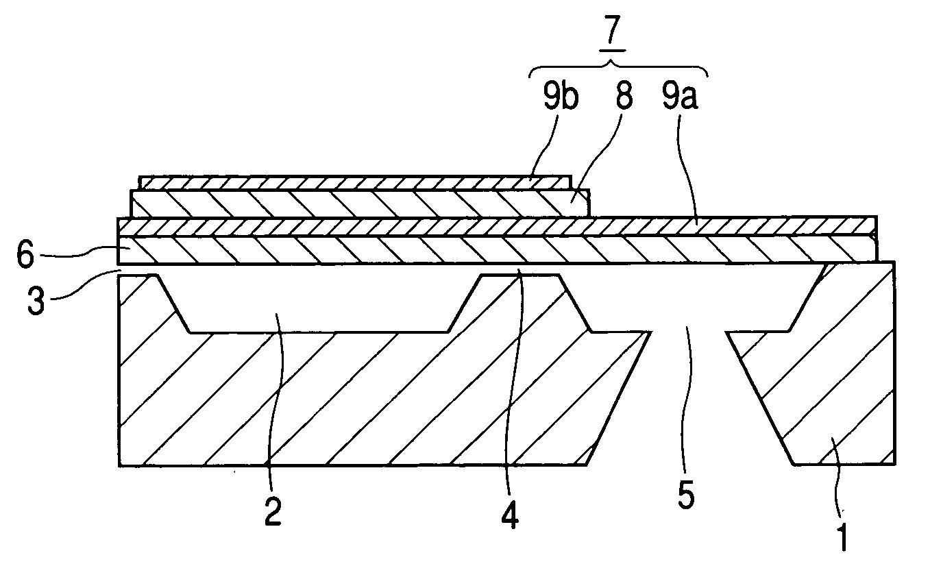
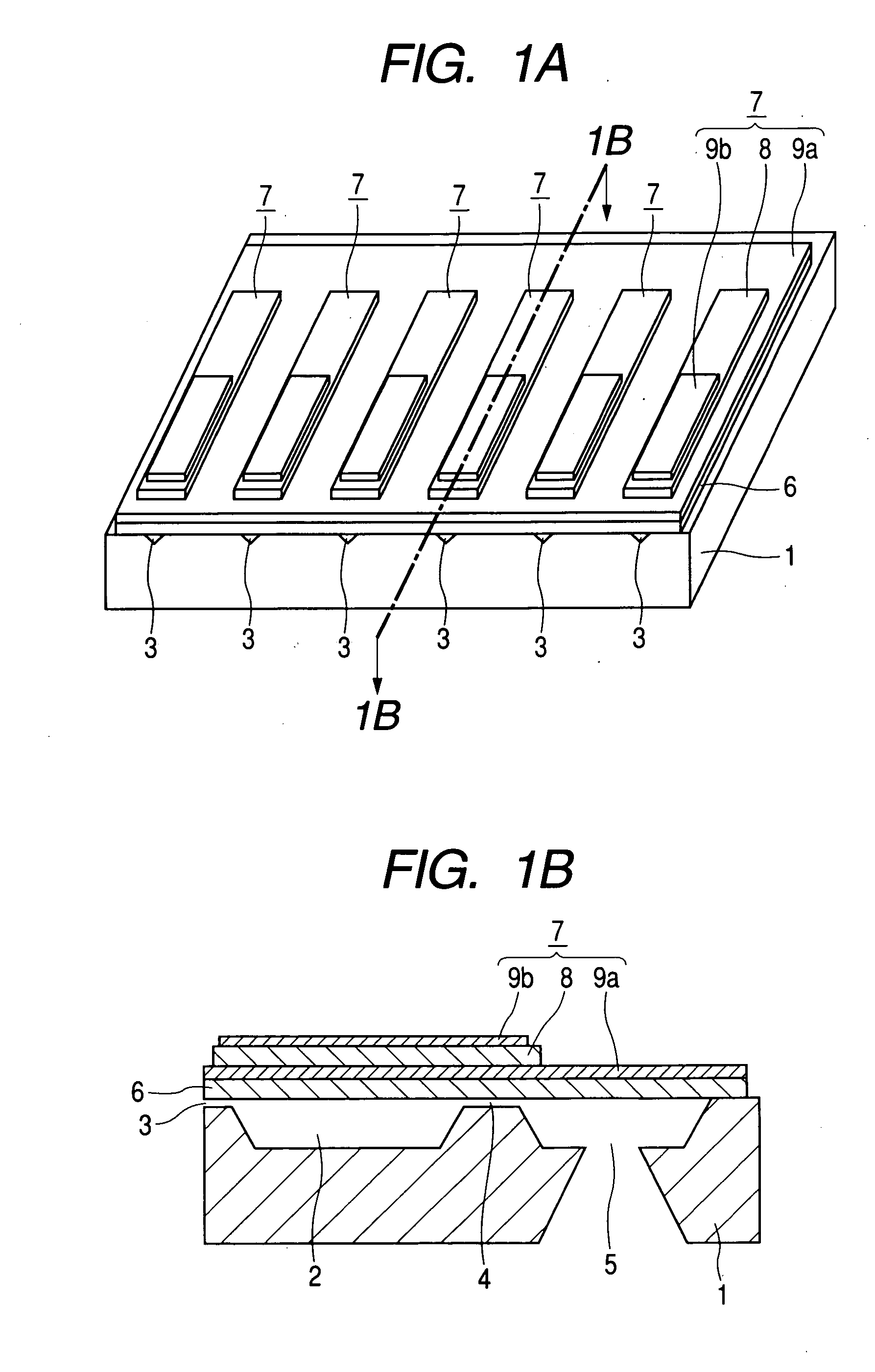
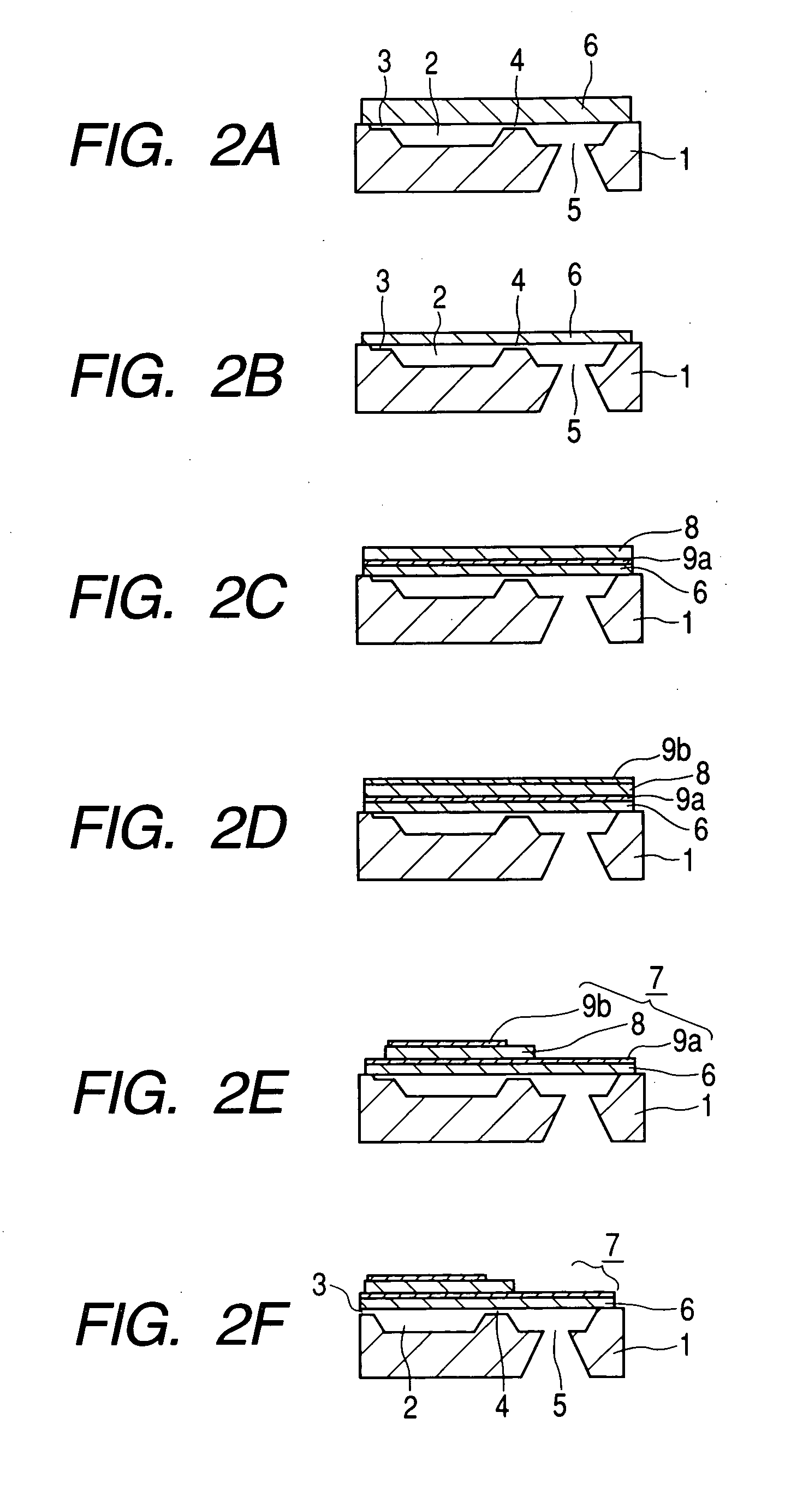
[0072] In this embodiment, RF sputtering was used as a method of depositing the piezoelectric film 8, a glass substrate 6a from which a glass diaphragm 6 is formed and which is made of aluminosilicate glass SD2 (manufactured by HOYA Co., Ltd) was anodically joined on a flow passage substrate 1 formed of an Si substrate which had been previously formed with a pressure generation chamber 2 and the like, and after being thinned by polishing, a PZT film serving as the piezoelectric film 8 was deposited on the glass diaphragm 6 through the intermediary of a lower electrode without heating, and thereafter, it was sintered for crystallization. The transition point of aluminosilicate glass SD2 (manufactured by HOYA Co., Ltd) 720° C. and the strain point is 670° C.

[0073] At first, a groove or the like serving as a nozzle was formed on an Si (100) substrate with the use of an anisotropic etching technology. The groove has a triangular prism-like shape, and further, a pressure generation cham...

embodiment 2

[0078] In this embodiment, RF sputtering was used as a method of depositing the piezoelectric film 8, a glass substrate 6a from which a glass diaphragm 6 is formed and which is made of aliminosilicate glass SD2 (manufactured by HOYA Co., Ltd) was anodically joined on a flow passage substrate 1 formed of an Si substrate which had been previously formed with a pressure generation chamber 2 and the like, and a PZT film serving as the piezoelectric film 8 of a piezoelectric element 7 was deposited on the glass diaphragm 6 while it was heated for crystallization.

[0079] At first, a groove or the like serving as a nozzle was formed on an Si (100) substrate with the use of an anisotropic etching technology. The groove has a triangular prism-like shape, and further, a pressure generation chamber, an orifice, a liquid supply chamber and the like were formed. Then, an aluminosilicate glass substrate from which a glass diaphragm is formed, having a thickness of 30 μm was joined to on the groov...

embodiment 3

[0096] As a flow passage substrate 1 in the liquid discharge head shown in FIGS. 5A and 5B, an Si substrate formed therein grooves, as shown in FIGS. 6A and 6B, serving as a pressure chamber 2, nozzles 3, an orifice 4 and a liquid discharge chamber 5 was used, and was anodically joined thereto with aluminosilicate glass SD2 (Trade Mark belonging to HOYA co., Ltd) from which a diaphragm 6 is formed, then an MgO film having an extremely large thermal expansion coefficient was deposited thereon as an intermediate film by RF sputtering, and a PZT film serving as the piezoelectric film 8 was deposited thereon without heating, and was then sintered so as to obtain an unimorph type piezoelectric element.

[0097] At first, a groove or the like serving the pressure chamber was formed on an Si (100) substrate with the use of an anisotropic etching technology. The groove has a triangular prism-like shape, as viewed in the direction of the nozzle, as shown in FIG. 6B. Then, an aluminosilicate gl...


PUM

PropertyMeasurementUnit
Thicknessaaaaaaaaaa
Temperatureaaaaaaaaaa
Thicknessaaaaaaaaaa

Abstract

In a method of manufacturing a liquid discharge head, liquid in a pressure generation chamber is pressurized by a piezoelectric driving force of a piezoelectric element, and is discharged from a nozzle communicated with the pressure generation chamber. The method is characterized by the steps of providing a flow passage substrate incorporating the pressure generation chamber, anodically joining a diaphragm to the flow passage substrate, forming electrode layers and a piezoelectric film of the piezoelectric element on the diaphragm, and crystallizing the piezoelectric film during or after the lamination at a crystallization temperature not higher than a strain point of the diaphragm.

Description

BACKGROUND OF THE INVENTION [0001] 1. Field of the Invention [0002] The present invention relates to a liquid discharge head incorporating a unimorph type piezoelectric element using a piezoelectric thin film (piezoelectric film) and a method of manufacturing thereof, and also a method of manufacturing a piezoelectric element. The present invention can apply to any of various devices using a driving force of a piezoelectric element, including a liquid discharge head incorporated in a recording apparatus such as a printer. [0003] 2. Description of the Related Art [0004] These years, the studies of devices using functional thin films have been prosperous, and it has been expected to materialize excellent functions by forming a functional material into a thin-film which is incorporated in any of various devices. [0005] For example, studies of devices including piezoelectric elements, sensors, nonvolatile memories and the like, using physical properties such as piezoelectricity, pyroele...

Claims


Application Information

Patent Timeline
IPC IPC(8): B41J2/16
CPCB41J2/161B41J2/1623B41J2/1628B41J2/1629Y10T29/49155B41J2/1646Y10T29/42Y10T29/49401B41J2/1632
Inventor WADA, TAKATSUGUAKAIKE, MASATAKE
Owner CANON KK
Features
  • Generate Ideas
  • Intellectual Property
  • Life Sciences
  • Materials
  • Tech Scout
  • Unparalleled Data Quality
  • Higher Quality Content
  • 60% Fewer Hallucinations
Learn More