

Heat storing material, composition thereof and their use
a technology of heat storage material and storing material, applied in the field of heat storage material, can solve the problems of leakage or spillage, low boiling point, and the inability of microcapsules to exhibit their function, and achieve the effect of preventing excessive heating or cooling
- Summary
- Abstract
- Description
- Claims
- Application Information
AI Technical Summary
Benefits of technology
Problems solved by technology
Method used
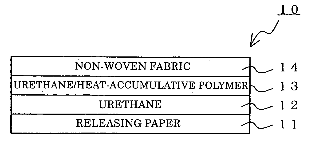
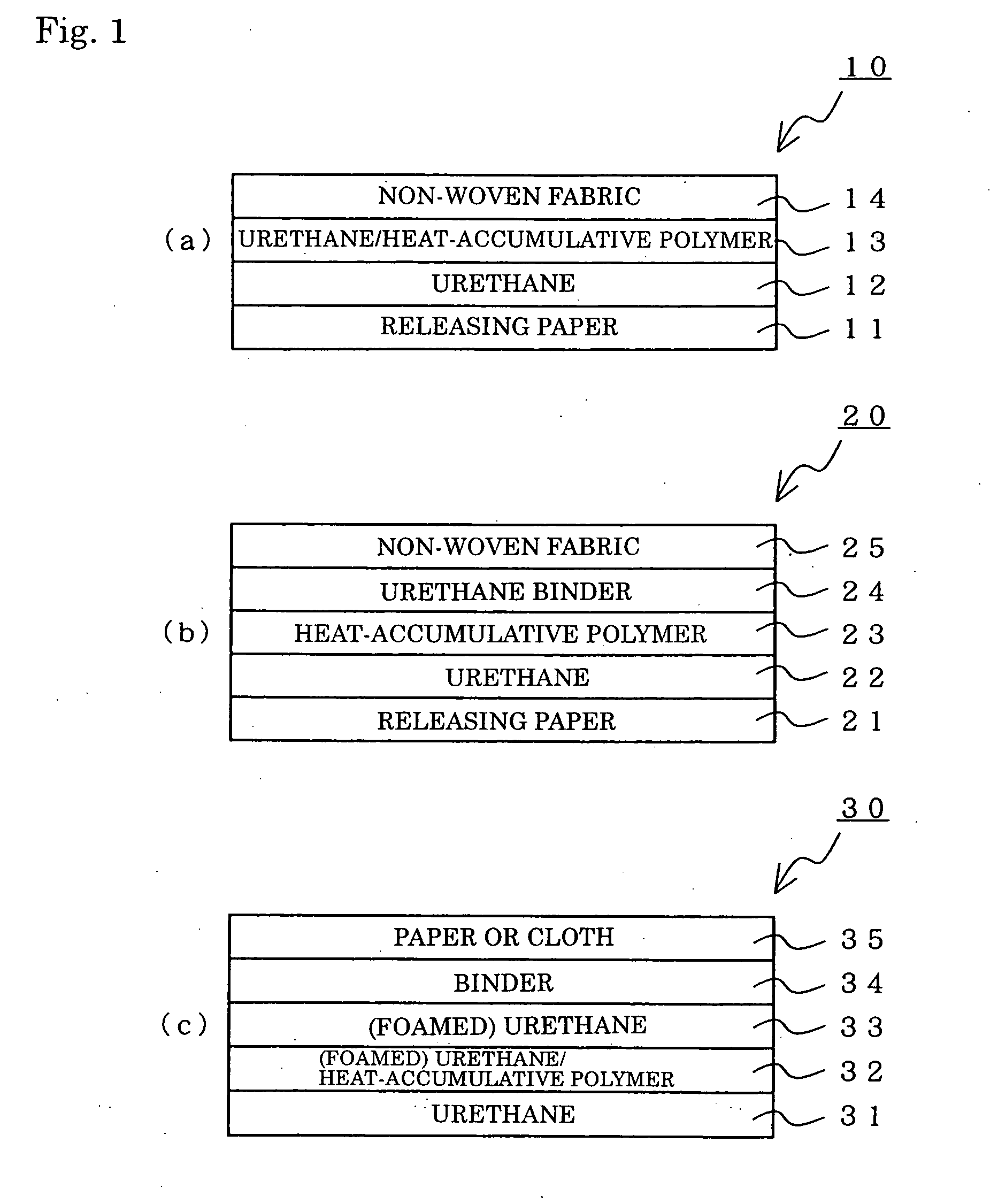
Image

Examples
example 1
[0178] Polystearyl methacrylate was synthesized by the following procedure.
[0179] (1) A 2 L four-mouthed separable flask, equipped with a nitrogen supply tube, stirrer and reflux system, was charged with 400 g of stearyl methacrylate as a monomer and 700 mL of THF as a solvent.
[0180] (2) While nitrogen was fed into the flask, the content of the flask, put in a water bath kept at 70° C., was heated with slowly stirring to dissolve the monomer.
[0181] (3) After the monomer was dissolved, 0.1 g of azobisisobutylonitrile (hereinafter abbreviated to AIBN) as a polymerization initiator was added to the flask, and the stirring was then continued. Nitrogen was blown to such an extent that THF could be refluxed.
[0182] (4) In 1 hour, temperature of the water bath was adjusted in such a way to keep the flask inside at 70 to 75° C., at which the reaction process was allowed to proceed for 7 to 9 hours, to prepare a reaction solution.
[0183] (5) The resulting reaction solution was poured litt...
example 2
[0188] Polystearyl methacrylate was synthesized in the same manner as in EXAMPLE 1, except that THF as a solvent was replaced by toluene.
[0189] It had a weight-average molecular weight of 610,000.
[0190] Its various properties were measured. The results are given in Table 2.
example 3
[0191] Polystearyl methacrylate was synthesized in the same manner as in EXAMPLE 2, except that quantity of AIBN added was changed to 0.2 g.
[0192] It had a weight-average molecular weight of 330,000.
[0193] Its various properties were measured. The results are given in Table 2.
PUM
| Property | Measurement | Unit |
|---|---|---|
| melting point | aaaaa | aaaaa |
| melting point | aaaaa | aaaaa |
| melting point | aaaaa | aaaaa |
Abstract
Description
Claims
Application Information