Parts manipulation and inspection system and method

Inactive Publication Date: 2005-05-26
LEMAIRE CHARLES A
View PDF42 Cites 47 Cited by
  • Summary
  • Abstract
  • Description
  • Claims
  • Application Information

AI Technical Summary

Benefits of technology

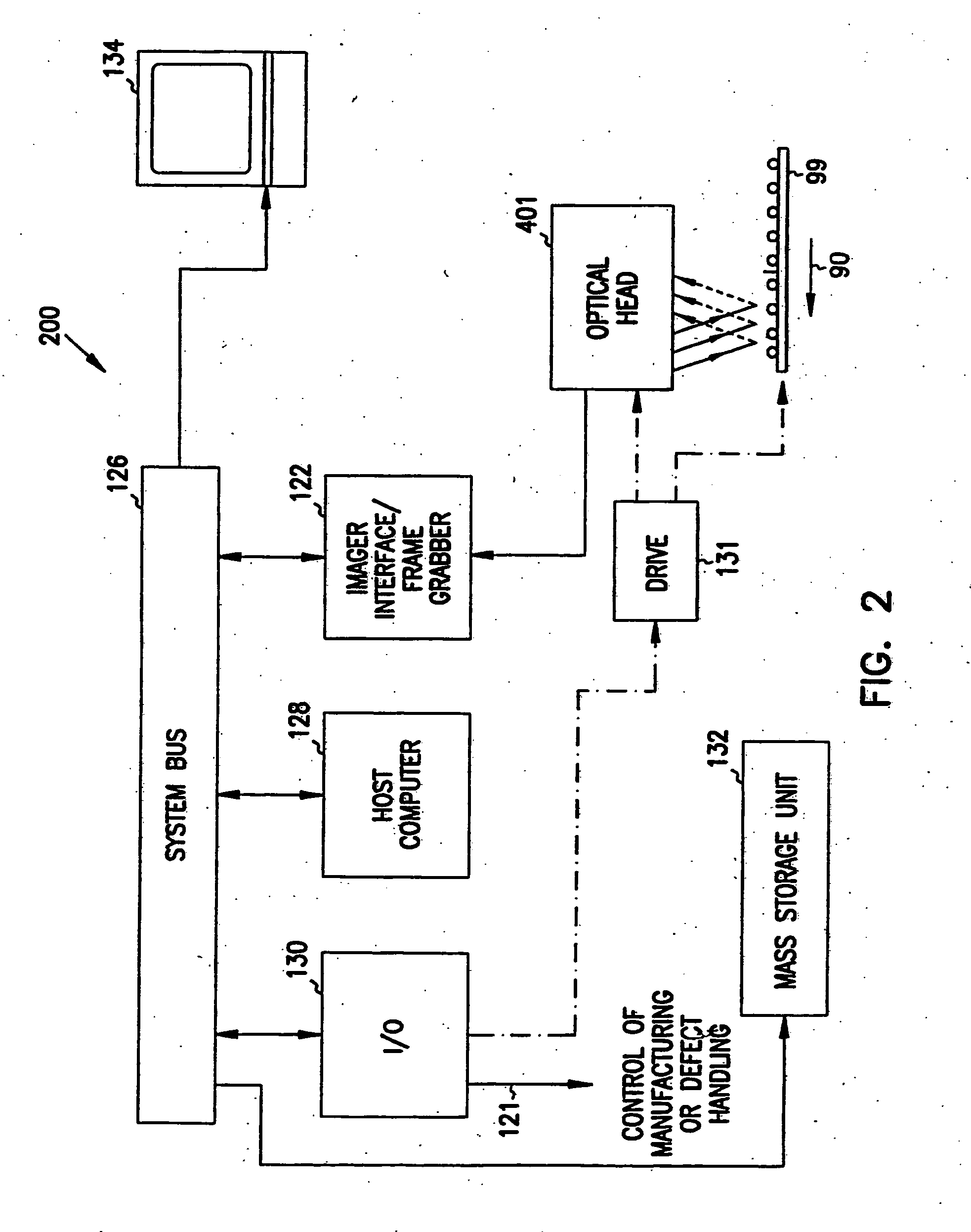
[0027] Advantageously, this invention solves or lessens many of the problems associated with current vision inspection systems. A feedback loop is used to control the intensity of the light received at a light receiver. This reduces the variability of the light intensity received at the light receiver. This eases the task of correlating signals generated by the receiver. Within a CCD the individual sources of light may be controlled to control the gain and bias resulting from manufacturing variances. This also

Problems solved by technology

Current vision inspection systems have many problems.
Among the problems are that the intensity of the light received at a light receiver may vary.
When the intensity of the light varies at the receiver, it is very difficult to correlate signals that are generated by the receiver.
Another problem is that the light receiver may vary in temperature.
CCDs tend to heat up as they operate.
When the currents associated with dark areas get too large, the current shows up as

Method used


Image

  • Parts manipulation and inspection system and method
  • Parts manipulation and inspection system and method
  • Parts manipulation and inspection system and method

Examples


Embodiment Construction

[0070] In the following detailed description of the preferred embodiments, reference is made to the accompanying drawings which form a part hereof, and in which are shown by way of illustration specific embodiments in which the invention may be practiced. It is to be understood that other embodiments may be utilized and structural changes may be made without departing from the scope of the present invention.

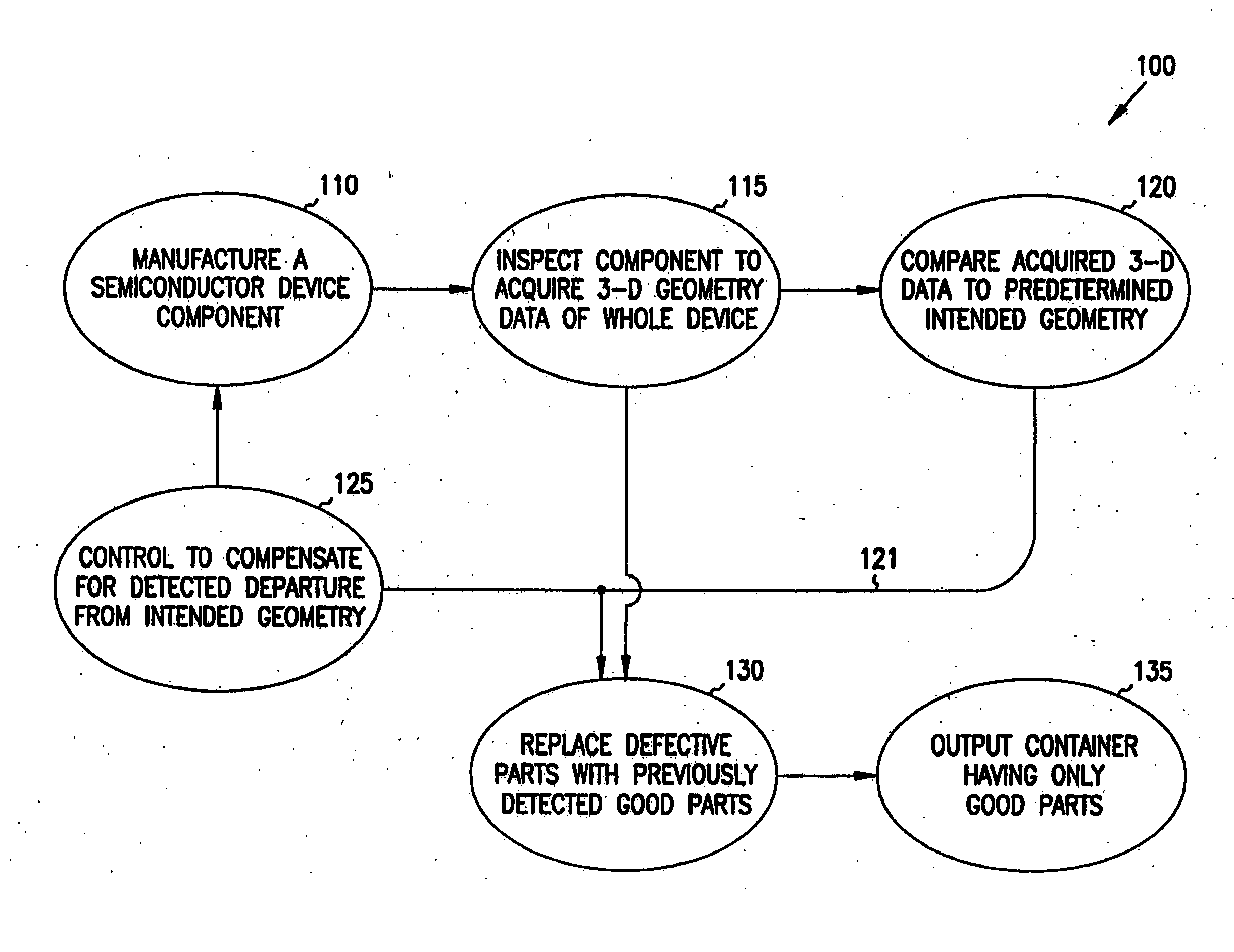
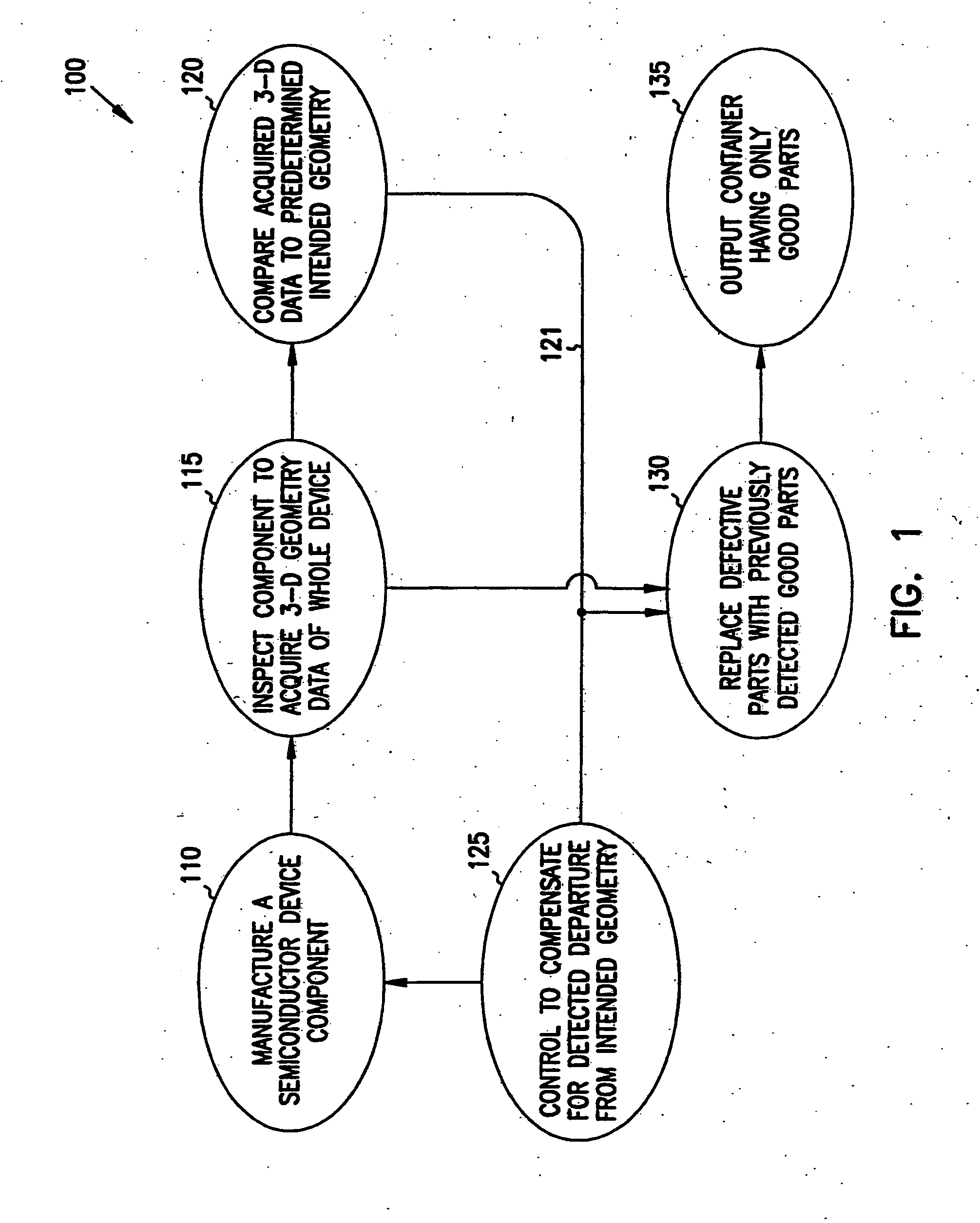
[0071] Machine-vision and optical-feature-recognition techniques can be used to distinguish parts that deviate from a predetermined intended aspect of an ideal device. In this description, a “device” is meant to be any device of manufacture or object, for example an integrated circuit package, electronic part, semiconductor, molded plastic part, aluminum wheel, gemstone or even an egg or strawberry, which can be inspected. Typically, according to the present invention, a manufacturing operation will use two-dimensional and three-dimensional information acquired from section of t...


PUM


Abstract

Manufacturing lines include inspection systems for monitoring the quality of parts produced. Manufacturing lines for making semiconductor devices generally inspect each fabricated part. The information obtained is used to fix manufacturing problems in the semiconductor fab plant. A machine-vision system for inspecting devices includes a light source for propagating light to the device and an image detector that receives light from the device. Also included is a light sensor assembly for receiving a portion of the light from the light source. The light sensor assembly produces an output signal responsive to the intensity of the light received at the light sensor assembly. A controller controls the amount of light received by the image detector to a desired intensity range in response to the output from the light sensor. The image detector may include an array of imaging pixels. The imaging system may also include a memory device which stores correction values for at least one of the pixels in the array of imaging pixels. To minimize or control thermal drift of signals output from an array of imaging pixels, the machine-vision system may also include a cooling element attached to the imaging device. The light source for propagating light to the device may be strobed. The image detector that receives light from the device remains in a fixed position with respect to the strobed light source. A translation element moves the strobed light source and image detector with respect to the device. The strobed light may be alternated between a fit and second level.

Description

RELATED APPLICATIONS [0001] This application is a divisional of U.S. patent application Ser. No. 09 / 757,834, entitled “IMAGING FOR A MACHINE VISION SYSTEM,” which is a continuation of PCT application PCT / US99 / 15411, which claims the benefit of U.S. Provisional Application Ser. No. 60 / 092,089, filed Jul. 8, 1998, under 35 U.S.C. 119(e). The present invention is related to: [0002] U.S. Pat. No. 6,603,103, entitled “CIRCUIT FOR MACHINE-VISION SYSTEM,”[0003] U.S. patent application Ser. No. 09 / 350050, entitled “MACHINE-VISION SYSTEM AND METHOD FOR RANDOMLY LOCATED PARTS” (Attorney Docket No. 139.041 US1, now abandoned), [0004] U.S. patent application Ser. No. 09 / 350255, entitled “PARTS MANIPULATION AND INSPECTION SYSTEM AND METHOD” (Attorney Docket No. 139.042US 1, now abandoned), [0005] U.S. patent application Ser. No. 09 / 349684, entitled “MACHINE-VISION SYSTEMS AND METHODS WITH UP AND DOWN LIGHTS” (Attorney Docket No. 139.052US1, now abandoned), [0006] U.S. patent application Ser. No....

Claims


Application Information

Patent Timeline
IPC IPC(8): G01B11/25G01N21/956G03F7/20H01L21/00
CPCG01B11/2513G01B11/2518H01L21/00G03F7/70483G06T7/0057G01N21/95607G06T7/521
Inventor HACKNEY, JOSHUA J.MALEK, ARYEULRICH, FRANZ W.ESTRIDGE, JOHN
Owner LEMAIRE CHARLES A
Why Eureka
Try Eureka