Fuel cell, fuel cell electrode and method for fabricating the same

a fuel cell and electrode technology, applied in the direction of cell components, final product manufacturing, sustainable manufacturing/processing, etc., can solve the problems of inability to obtain excellent cell characteristics, inability to obtain cell worth evaluating, and inability to meet the requirements of a single cell performan

Inactive Publication Date: 2005-05-26
NEC CORP
View PDF2 Cites 35 Cited by
  • Summary
  • Abstract
  • Description
  • Claims
  • Application Information

AI Technical Summary

Benefits of technology

[0078] While a method of fabricating the membrane electrode assembly of the present Embodiment is not especially restricted, the assembly may be fabricated as follows.
[0079] At first, catalyst is supported on carbon particles. This process can be conducted by the generally-used impregnation method. Then, the fuel electrode 102 and the oxidant electrode 108 formed with the catalyst layer 106 and the catalyst layer 112, respectively, can be fabricated by dispersing the carbon particles supporting the catalyst and the first solid polymer electrolyte into a solvent to make a paste and applying the paste on the substrates followed by drying. The particle size of the carbon particles is adjusted to be, for example, 0.001 to 0.1.m. The particle size of the catalyst particles is adjusted to be, for example, 0.1 nm to 100 nm. The particle sizes of the first and the second solid polymer electrolytes are, for example, 0.05 to 100.m. The carbon particles and the solid polymer electrolyte particles are used, for example, in a weight ratio from 1:5 to 40:1. The weight ratio between the water and the dissolved substance in the paste is adjusted to be, for example, from 1:2 to 10:1. While a method of applying the paste on the substrate is not especially restricted, brush application, spray application and screen printing can be used, for example. The paste is applied with thickness of about 1.m to 2 mm. After the application of the paste, it is dried at a heating temperature for a specified length of heating depending on the first solid polymer electrolyte used. While the heating temperature and the specified length of heating are suitably selected depending on the material used, the heating temperature is 100. to 250., and the specified length of heating is 30 seconds to 30 minutes, for example.
[0080] The solid polymer electrolyte membrane 114 of the present invention can be fabricated by using a method suitable for material used. For example, it is obtained by casting liquid prepared by dissolving or dispersing an organic polymer material into a solvent on an exfoliation sheet made of polytetrafluoroethylene followed by drying.
[0081] Then, the adhesion layer 161 is formed. The adhesion layer 161 can be formed by applying an application liquid having dissolved or dispersed second solid polymer electrolyte on the catalyst layer 106 or the catalyst layer 112 and / or the surface of the solid polymer electrolyte membrane 114 followed by drying. When the application liquid is applied on the solid polymer electrolyte membrane 114, the process is conducted on both of the surfaces of the solid polymer electrolyte membrane 114. In this case, for example, after the application liquid is applied on one surface of the solid polymer electrolyte membrane 114 and the surface is covered with an exfoliation sheet made of polytetrafluoroethylene, the application liquid may be applied on the other surface of the solid polymer electrolyte membrane. Thereby, the solid polymer electrolyte membrane 114 having the adhesion layers 161 on the both surfaces can be obtained.
[0082] In the present Embodiment, although the adhesion layers 161 are present in the two regions or between the solid polymer electrolyte membrane 114 and the fuel electrode 102 and between the solid polymer electrolyte membrane 114 and the oxidant electrode 108, the adhesion layer may be present in one of the two regions. The adhesion layer of the present invention is not necessarily formed on the entire surface of the region, and may be formed in at least part of the region. For example, the adhesion layer 161 may be formed in an island shape. Thickness of the adhesion layer 161 is suitably selected in a range, for example, from 0.1.m to 20.m.
[0083] The solid polymer electrolyte membrane thus fabricated is sandwiched between the fuel electrode 102 and the oxidant electrode 108 and hot-pressed to provide the membrane electrode assembly. At this time, the surfaces of the both electrodes having the catalyst thereon are disposed to oppose to the solid polymer electrolyte membrane 114 sandwiching the adhesion layers 161. The conditions of the hot-pressing are selected depending on the material, and, for example, a temperature thereof exceeds the softening temperatures and the glass transition temperatures of the first solid polymer electrolyte and the second solid polymer electrolyte. Specifically, the temperature is between 100 and 250., the pressure is between 5 and 100 kgf / cm2, and the length of time is between 10 seconds and 300 seconds.

Problems solved by technology

However, the cell performances of the above fuel cell were lower than those of the conventional cell using the Nafion.
The excellent cell characteristics could not be obtained probably because the solid polymer electrolyte did not sufficiently satisfy these performances in the cell having the above structure.
However, the fuel electrode and the solid polymer electrolyte membrane were insufficiently bonded with each other, and the cell worth evaluating could not be obtained.

Method used


Image

  • Fuel cell, fuel cell electrode and method for fabricating the same
  • Fuel cell, fuel cell electrode and method for fabricating the same
  • Fuel cell, fuel cell electrode and method for fabricating the same

Examples


embodiment

[0061] First to third Embodiments of the present invention will be hereinafter described in detail.

first embodiment

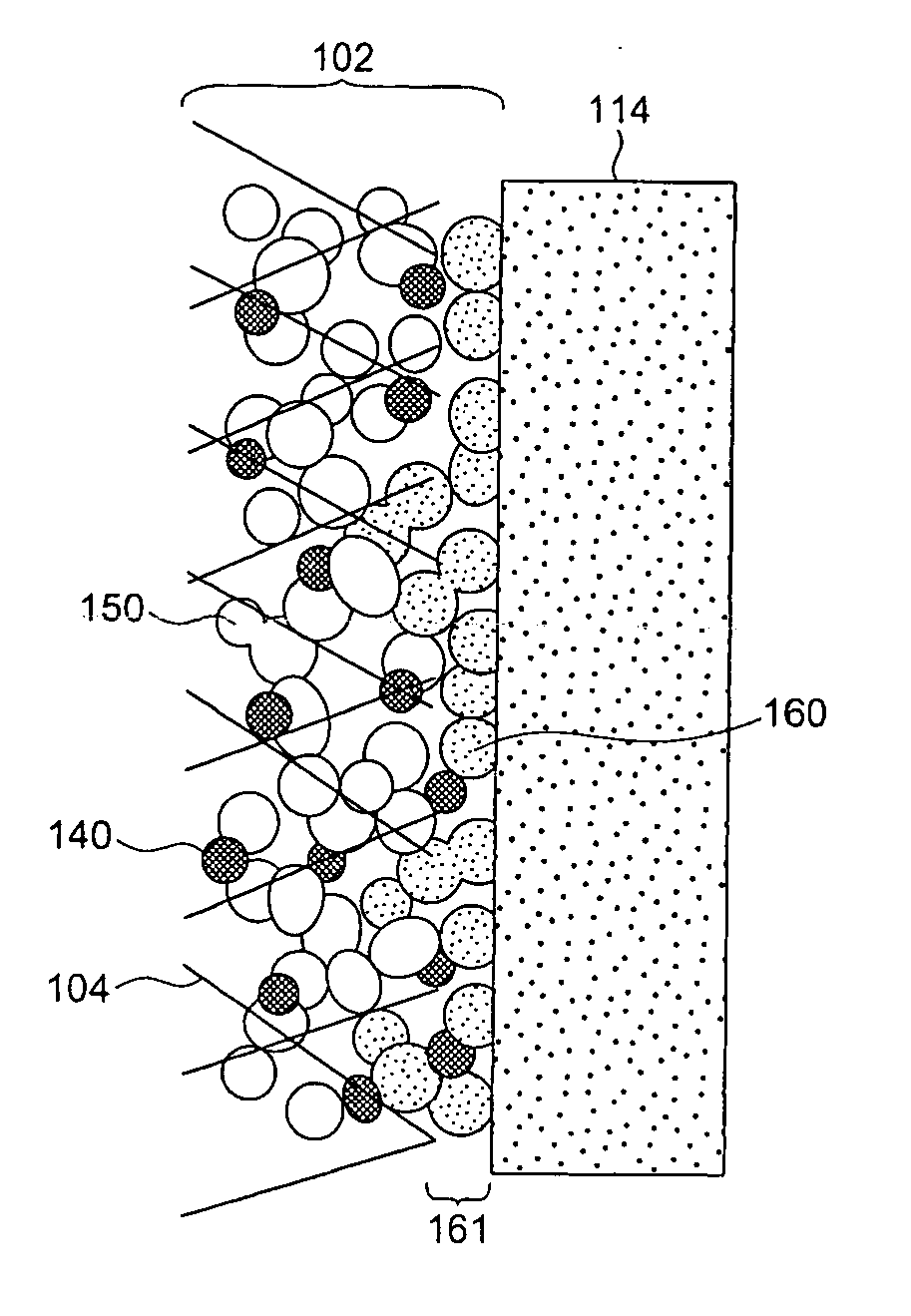
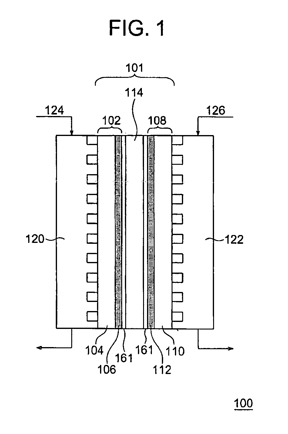
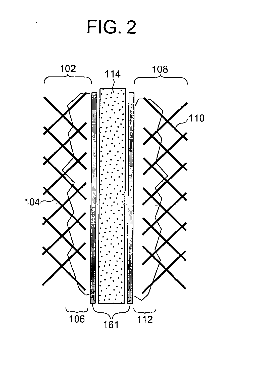
[0062] As shown in FIG. 1, in a fuel cell of the present Embodiment, a membrane electrode assembly 101 is configured by a fuel electrode 102, an oxidant electrode 108 and a solid polymer electrolyte membrane 114. The fuel electrode 102 is configured by a substrate 104 and a catalyst layer 106. The oxidant electrode 108 is configured by a substrate 110 and a catalyst layer 112. Respective adhesion layers 161 are disposed between the solid polymer electrolyte membrane 114 and the fuel electrode 102 and between the solid polymer electrolyte membrane 114 and the oxidant electrode 108. A plurality of the membrane electrode assemblies 101 are electrically connected among one another through fuel electrode-side separators 120 and oxidant electrode-side separators 122, thereby fabricating the fuel cell 100.

[0063] The fuel electrode 102 and the oxidant electrode 108 have configurations including the catalyst layer 106 and the catalyst layer 112, respectively, each containing the catalyst an...

second embodiment

[0096] The present Embodiment is different from the first Embodiment in that the adhesion layer 161 also contains catalyst and carbon particles supporting the catalyst.

[0097] While a method of fabricating the membrane electrode assembly of the present Embodiment is not especially restricted, the assembly may be fabricated as follows.

[0098] The catalyst layer 106 or the catalyst layer 112 can be fabricated similarly to the first Embodiment. The adhesion layer 161 can be formed by applying a paste-like application liquid prepared by dispersing the second solid polymer electrolyte and carbon particles supporting the catalyst into a solvent, on the catalyst layer 106 or the catalyst layer 112 and / or the surface of the solid polymer electrolyte membrane 114 followed by drying. The carbon particles and the solid polymer electrolyte particles in the application liquid are used, for example, in a weight ratio from 1:5 to 40:1. In this manner, the adhesion layer 161 containing the carbon p...


PUM

PropertyMeasurementUnit
particle sizeaaaaaaaaaa
particle sizesaaaaaaaaaa
thicknessaaaaaaaaaa

Abstract

An adhesion layer containing a second solid polymer electrolyte is disposed between a solid polymer electrolyte membrane and a fuel electrode and/or an oxidant electrode containing a first solid polymer electrolyte and a catalyst substance. The solid polymer electrolyte membrane and the adhesion layer are made of the same solid polymer electrolyte. In this manner, the adhesion at the interface between the electrode surface and the solid polymer electrolyte membrane is enhanced to implement the elevation of the cell characteristics and the elevation of the reliability of the cell.

Description

CROSS-REFERENCE TO RELATED APPLICATION [0001] The present application is a continuation of International Application No. PCT / JP03 / 04819 which was filed on Apr. 16, 2003, which is herein incorporated by reference.TECHNICAL FIELD [0002] The present invention relates to a fuel cell, a fuel cell electrode and a method for fabricating the same. BACKGROUND ART [0003] A solid polymer fuel cell is a power-generating apparatus wherein hydrogen and oxygen are supplied to the fuel electrode and the oxidant electrode, respectively. The fuel electrode and the oxidant electrode are bonded to the respective surfaces of a solid polymer electrolyte membrane containing perfluorosulfonic acid acting as an electrolyte. [0004] The following reactions take place in the respective electrodes. [0005] Fuel Electrode: H2.2H++2e. [0006] Oxidant Electrode: 1 / 2O2+2H++2e.H2O [0007] Higher power of 1 A / cm2 or more can be obtained at ambient temperatures and atmospheric pressure in accordance with the reactions in...

Claims


Application Information

Patent Timeline
Patent Type & Authority Applications(United States)
IPC IPC(8): H01M4/86H01M4/88H01M8/02H01M8/10
CPCH01M4/8605Y02E60/521H01M4/8828H01M4/8882H01M8/0291H01M8/1004H01M8/1011H01M8/1023H01M8/1025H01M8/1039H01M8/1051H01M8/1053H01M8/109H01M2300/0082H01M2300/0094H01M4/8668H01M8/0289Y02E60/50Y02P70/50
Inventor NAKAMURA, SHINKUBO, YOSHIMISHIMAKAWA, YUICHIMANAKO, TAKASHIKIMURA, HIDEKAZUIMAI, HIDETOKUROSHIMA, SADANORIYOSHITAKE, TSUTOMUOBATA, TAKESHI
Owner NEC CORP
Why Eureka
Try Eureka