Method and apparatus for modeling injection of a fluid in a mold cavity

a technology of injection molding and fluid flow, applied in the field of three-dimensional modeling of fluid flow in the cavity, can solve the problem that the accurate simulation of injection molding requires a typically non-isothermal analysis of the molten polymer, and achieve the effect of increasing the resolution

Inactive Publication Date: 2005-05-26
MOLDFLOW IRELAND LTD
View PDF36 Cites 50 Cited by
  • Summary
  • Abstract
  • Description
  • Claims
  • Application Information

AI Technical Summary

Benefits of technology

[0017] While conventional methods determine flow conductance at a plurality of small elements that divide the region in which fluid flows, according to one embodiment of the present invention, flow conductance is calculated at each of the nodes of each element. This technique allows a more precise value of the flow conductance to be defined, as the flow conductance may vary in any of a variety of desired fashions from node to node. The variation will depend on the type of finite element used to discretize the problem. Use of a nodal value is more desirable than use of an elemental value, as other quantities such as temperature, pressure, and velocity are more precisely defined as point values and, again, may be interpolated from node to node in any fashion. This interpolation capability also enables the location of the interface between the solid and molten polymer to be accurately determined, which has been found to be particularly relevant in simulation predictive accuracy.
[0020] In effect, by only calculating temperature, this reduces the number of variables to be determined to one in the frozen layer and thereby dramatically increases the speed of computation, while reducing the memory required. By removing the frozen nodes, the need for extrapolation of the viscosity is removed and so the errors associated therewith are removed as well. Further, by removing nodes in the frozen layer from the analysis, very small values of flow conductance are removed and the equations to be solved are better conditioned than in conventional methods. Still further, by not calculating fluid conductance in these regions, it has been found that not only is the problem size reduced considerably, but the stability of numerical methods is improved as well.
[0024] The discretizing step may include the substep of generating a finite element mesh based on the solid model by subdividing the model into a plurality of connected elements defined by a plurality of nodes. The mesh generating substep may include generating an anisotropic mesh in thick and thin zones of the model, such that mesh refinement provides increased resolution in a thickness direction without increasing substantially mesh refinement in a longitudinal direction.

Problems solved by technology

Accordingly, accurate simulation of injection molding requires typically non-isothermal analysis of the molten polymer as it flows into the mold.

Method used


Image

  • Method and apparatus for modeling injection of a fluid in a mold cavity
  • Method and apparatus for modeling injection of a fluid in a mold cavity
  • Method and apparatus for modeling injection of a fluid in a mold cavity

Examples


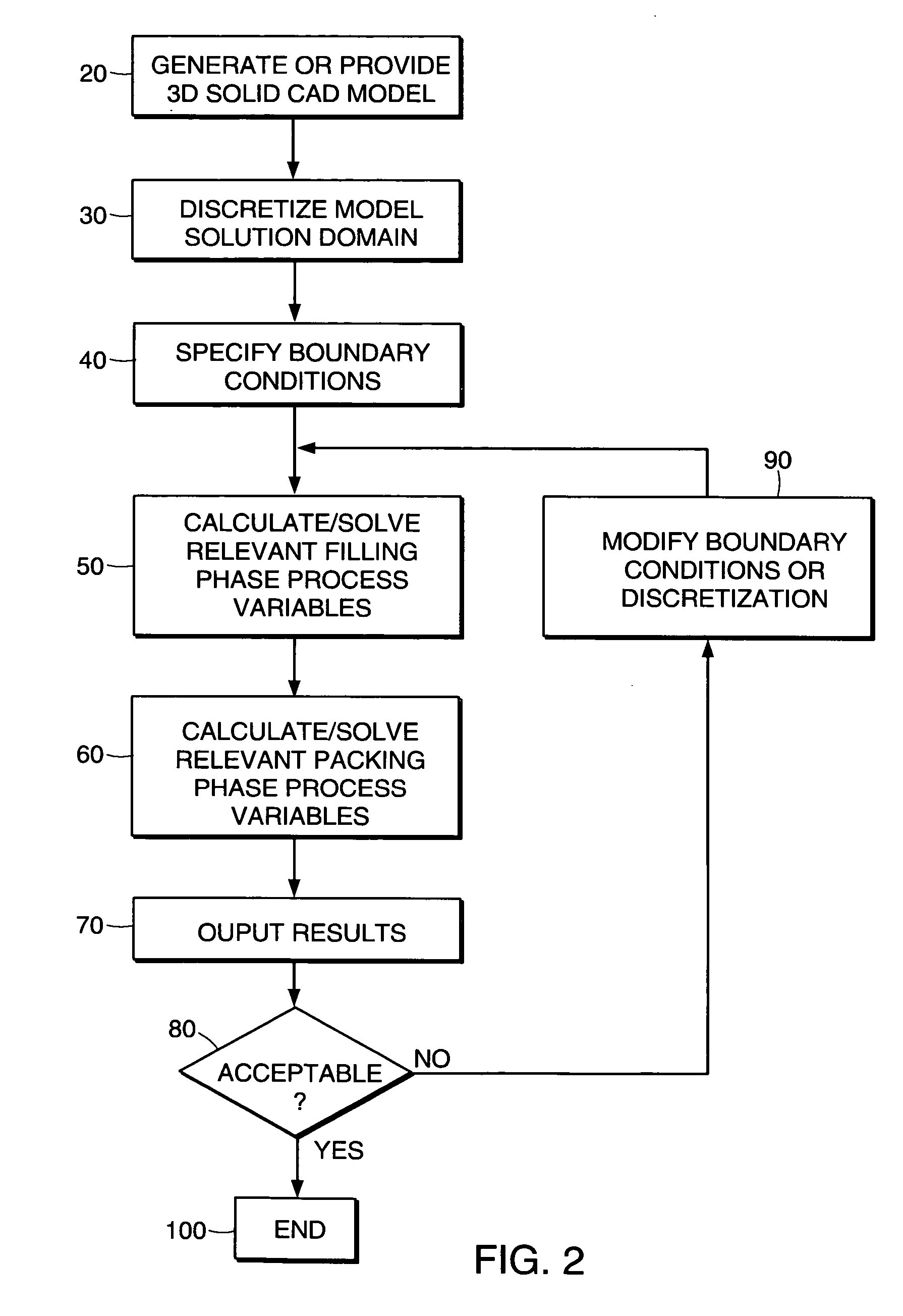
Embodiment Construction

[0062] Modeling of the injection molding process in a three dimensional simulation can be described by the conservation equations for mass, momentum, and energy, respectively, as follows: ∂ρ∂t+∇·(ρ⁢ ⁢v→)=0(3)

where ρ is density, v is velocity, t is time, ∇ stands for the gradient with respect to a position vector, and → denotes a vector quantity. ρ(∂v→∂t+v→·∇v→)+∇·P=ρ⁢ ⁢g→(4)

where P is the momentum flux and g is the gravity force. ρ(∂U^∂t+v->·∇U^)+P:D+∇·q->=ρ⁢ ⁢Q(5)

where U is specific internal energy, D is the deformation rate tensor, q is heat flux, and Q is the specific heat rate which signifies other heat sources or sinks.

[0063] Equation 4 is commonly expressed in terms of temperature and pressure, and for the case in which Q=0, i.e. no additional heat sources or sinks, typical for thermoplastics, takes the form, ρ⁢ ⁢Cp⁡(∂T∂t+v->·∇T)+Tρ⁢∂ρ∂T⁢(∂p∂t+v->·∇p)=η⁢ ⁢γ.2+∇·(κ⁢∇T)(6)

where Cp is specific heat, T is temperature, p is pressure, η is viscosity, is shear rate, and κ is...


PUM

PropertyMeasurementUnit
pressuresaaaaaaaaaa
pressuresaaaaaaaaaa
pressuresaaaaaaaaaa

Abstract

The invention relates to a method and apparatus for analyzing fluid flow while considering heat transfer effects and, in particular, a phase change from a molten state to a solid state. In particular, the method and apparatus may be applied to the analysis of an injection molding process for producing a molded polymer component from a thermoplastic or a thermosetting polymer. In one embodiment, the method may be used to determine pressure required to fill a mold cavity and pressure gradients introduced during filling and packing of the cavity of an injection mold. The results of these analyses may be used to determine the number and location of gates, to determine the best material for the component, and to optimize the process conditions used in the molding process.

Description

TECHNICAL FIELD [0001] The invention relates to the field of three dimensional modeling of fluid flow in a cavity and, more specifically in one embodiment, to the modeling of an injection molding process for producing molded polymer components. BACKGROUND [0002] The use of injection molded plastic components has dramatically increased in many industries in recent years. Manufacturers of electronic equipment, consumer goods, medical equipment, and automotive parts are producing more and more of their products and components used in their products out of plastics than ever before. At the same time, competitive pressures are driving manufacturers in the plastics injection molding industry to find new methods to optimize the designs in order to better match the designs to the production process. When the need for component or mold configuration modifications are discovered late in the design development process, the delay and associated costs to implement the necessary changes rise rapi...

Claims


Application Information

Patent Timeline
Patent Type & Authority Applications(United States)
IPC IPC(8): B29C33/38B29C45/76G06F17/50
CPCB29C33/3835B29C45/7693B29C2945/76006B29C2945/7605B29C2945/76381B29C2945/76531Y02T10/82B29C2945/76943B29C2945/76986G06F17/5018G06F2217/16G06F2217/41B29C2945/76775G06F2113/22G06F2111/10G06F30/23
Inventor FRIEDL, CHRISTIANCOSTA, FRANCO STEPHENCOOK, PETER SHANETALWAR, KAPILANTANOVSKII, LEONID K.
Owner MOLDFLOW IRELAND LTD
Why Eureka
Try Eureka