

Method for manufacturing a piezoelectric resonator
a manufacturing method and piezoelectric technology, applied in the direction of manufacturing tools, conductive pattern formation, device material selection, etc., can solve the problems of difficult to improve processing efficiency, difficult to form grooves with desired cross sectional shapes, slow dry etching speed, etc., to achieve the effect of removing the region irradiated evenly
- Summary
- Abstract
- Description
- Claims
- Application Information
AI Technical Summary
Benefits of technology
Problems solved by technology
Method used
Image

Examples
first embodiment
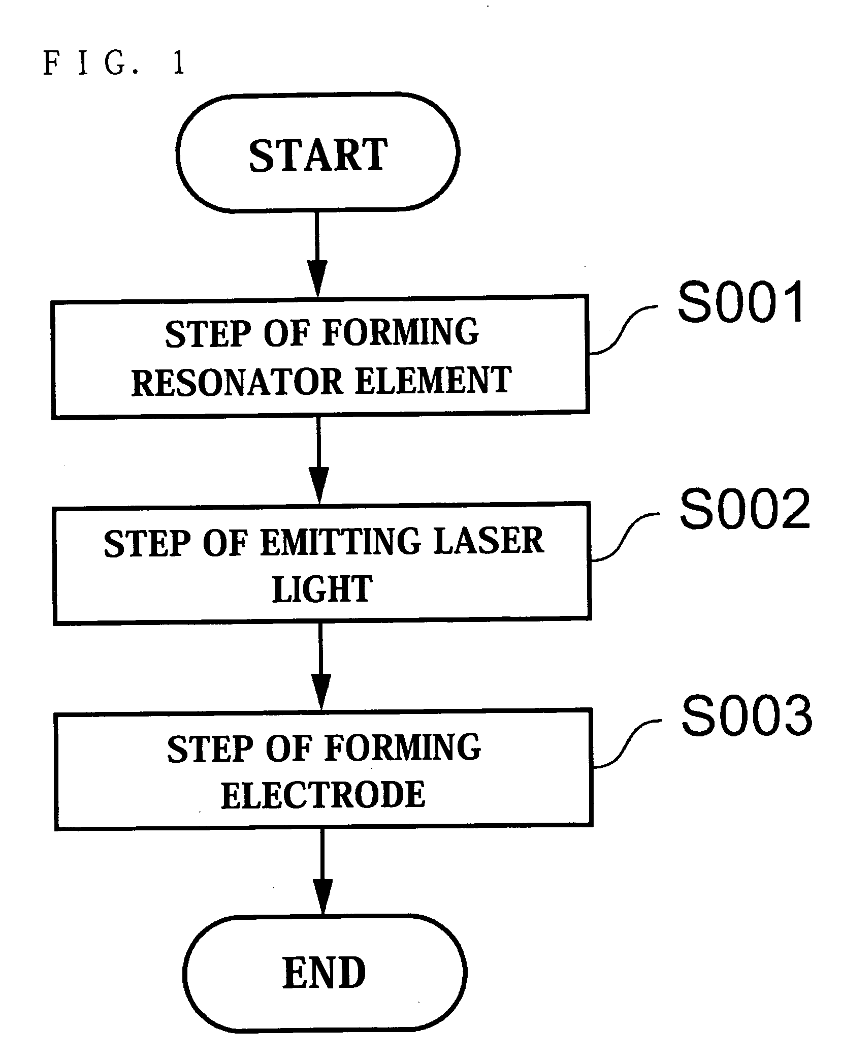
[0074] Referring to FIGS. 1 through 4 and 12 through 14, a first embodiment of the present invention will now be described.
[0075]FIG. 12 is a plan view schematically showing one surface of a piezoelectric resonator of the first embodiment. FIG. 13 is a plan view schematically showing the other surface of the piezoelectric resonator. FIG. 14 is a sectional view of the piezoelectric resonator along line A-A shown in FIG. 12.
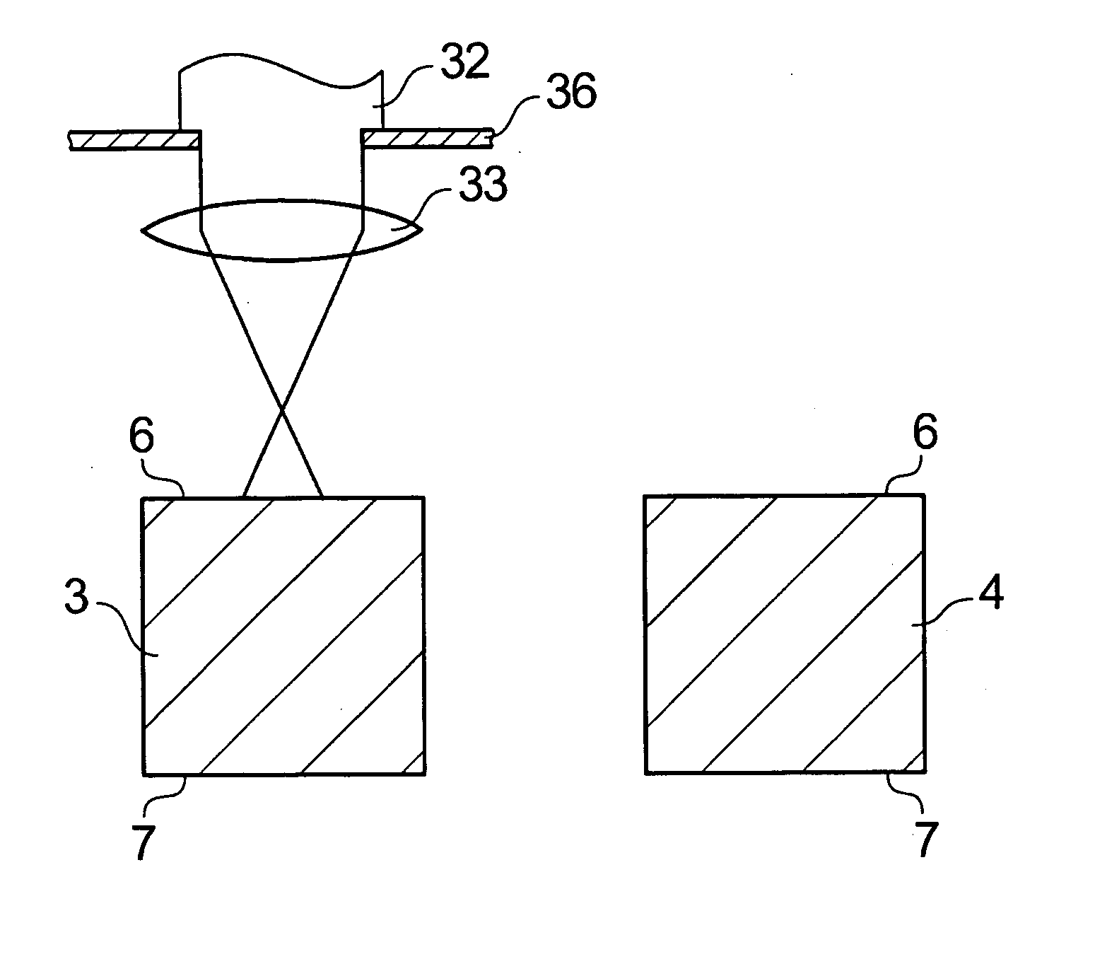
[0076] A piezoelectric resonator 1 according to the first embodiment is made of a crystal piezoelectric material, and as shown in FIGS. 12 and 13, includes a resonator element 5 having a plate-like base 2, and two arms 3, 4 extending laterally from the base 2 in the same direction in parallel with each other. In one surface 6 and the other (opposite) surface 7 of the arms 3, 4, grooves 8 through 11 extending longitudinally are provided. On the resonator element 5, a first driving electrode 12 and a second driving electrode 13 that give a voltage for driving the p...
second embodiment
[0096] Referring now to FIGS. 4 through 7 and 12 through 14, a second embodiment of the present invention will be described. The second embodiment provides a second method for manufacturing the piezoelectric resonator 1. Since the piezoelectric resonator 1 manufactured by the manufacturing method of the second embodiment has the same structure and appearance as those of the piezoelectric resonator 1 of the first embodiment, their descriptions will be omitted here.
[0097]FIG. 5 is a view showing steps of the second manufacturing method according to the second embodiment.
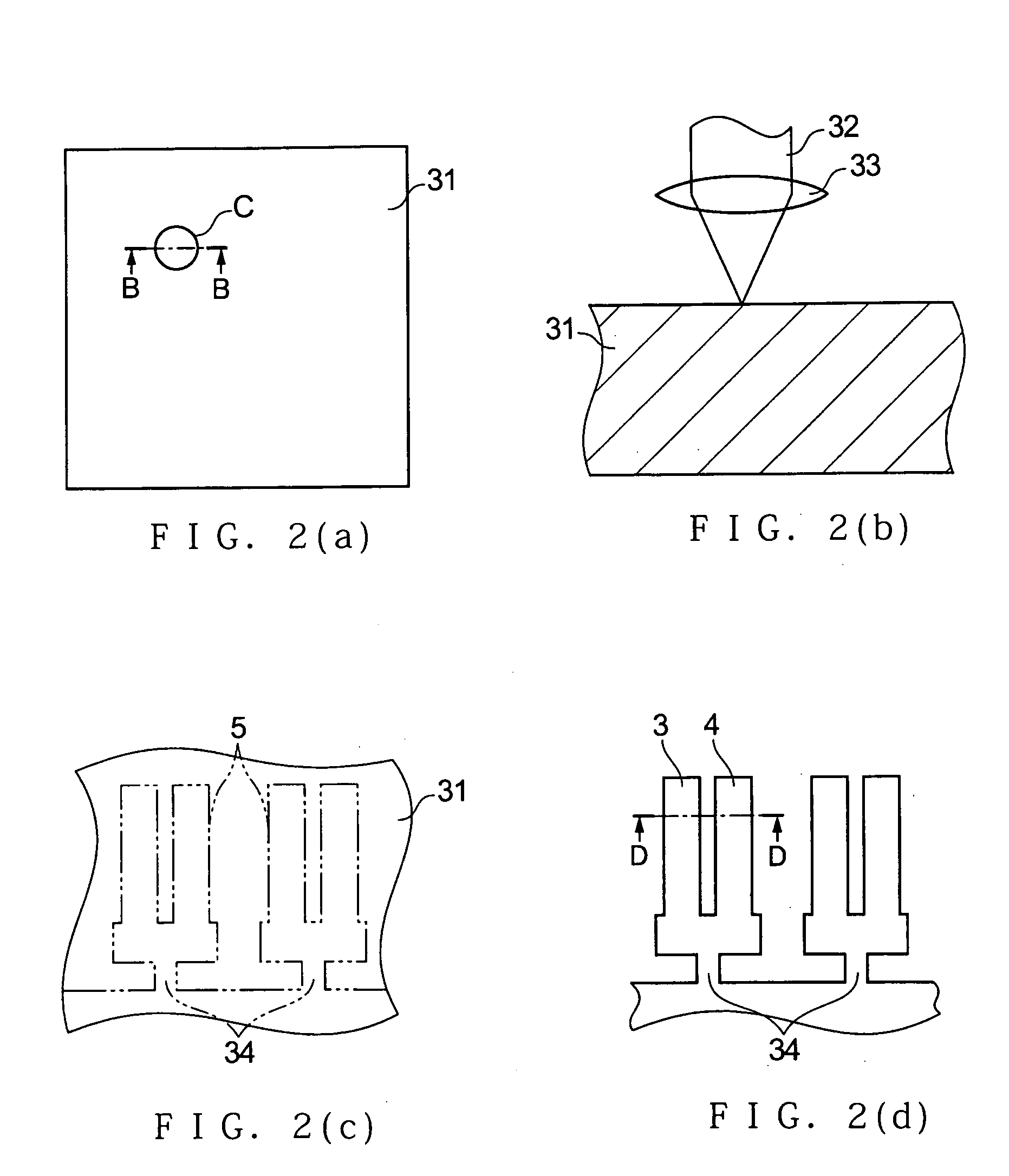
[0098] Referring to FIG. 5, the second manufacturing method includes step S004 for emitting laser light that forms the grooves 8 through 11 on the substrate 31 made of crystal, step S005 for forming a resonator element that forms the resonator element 5, and step S006 for forming an electrode that forms the first driving electrode 12 and the second driving electrode 13 on the resonator element 5, in this order.
[0099...
third embodiment
[0110] Referring now to FIGS. 1 through 4 and 15 through 17, a third embodiment of the present invention will be described.
[0111]FIG. 15 is a plan view schematically showing one surface of a piezoelectric resonator of the third embodiment. FIG. 16 is a plan view schematically showing the other surface of the piezoelectric resonator. FIG. 17 is a sectional view of the piezoelectric resonator along line H-H shown in FIG. 15.
[0112] A piezoelectric resonator 40 according to the third embodiment is made of a crystal piezoelectric material, and as shown in FIGS. 15 and 16, includes the resonator element 5 having the plate like base 2, and the two arms 3, 4 extending laterally from the base 2 in the same direction in parallel with each other. In the one surface 6 and the other surface 7 of the arms 3, 4, the grooves 8 through 11 extending longitudinally are provided. On the resonator element 5, a first driving electrode 41 and a second driving electrode 42 that give a voltage for driving...
PUM
| Property | Measurement | Unit |
|---|---|---|
| Shape | aaaaa | aaaaa |
| Electrical conductor | aaaaa | aaaaa |
| Electric potential / voltage | aaaaa | aaaaa |
Abstract
Description
Claims
Application Information