Frequency conversion circuit, radio frequency wave receiver, and radio frequency transceiver

a frequency conversion circuit and radio frequency wave receiver technology, applied in the direction of digital transmission, duplex signal operation, pulse technique, etc., can solve the problems of heterodyne radio frequency transceivers not being conventional radio frequency transceivers have a problem, and the heterodyne radio frequency transceiver cannot be fully mounted in the ic chip (integrated circuit), so as to reduce power consumption and noise, the effect of down

Inactive Publication Date: 2005-06-02
SHARP KK
View PDF5 Cites 55 Cited by
  • Summary
  • Abstract
  • Description
  • Claims
  • Application Information

AI Technical Summary

Benefits of technology

[0037] It is preferable to arrange so that the frequency conversion circuit further includes an image signal removal filter for removing an image signal from an output signal of the first mixer. It is preferable that the image signal removal filter can reduce, by 10 dB or greater, the image signal for the image frequency fIM (fIM=2fLO1−fRF) or for a frequency higher than the image frequency fIM.
[0058] Note that so called antenna switches per se, which are disclosed in the patent document 1 (indicated by a reference numeral “102”) and the non-patent document 2, for switching between the receiving mode and the transmitting mode do not reduce the power consumption.

Problems solved by technology

This is the well-known weakness of the heterodyne system.
However, the conventional radio frequency transceivers have a problem in being fully mounted in an integrated circuit (IC) or an IC chip as follows.
This results in that the heterodyne radio frequency transceiver cannot be fully mounted in the IC chip (integrated circuit).
This causes an increase in power consumption of the IC chip (integrated circuit).
The band-pass filter 15, however, hinders the heterodyne radio frequency transceiver from being mounted in an integrated circuit.
This causes the heterodyne radio frequency transceiver to be expensive, and to have extra power consumption.
Because the double conversion system is basically one of the heterodyne systems, the double conversion system also has the foregoing problems (i.e., the impossibility of the full mounting in an integrated circuit, and the increase in the power consumption of the integrated circuit).
Although the direct conversion system solves the problem of the image frequency, the direct conversion system has deterioration in sensitivity.
This is because the signal of the local oscillator leaks into a radio frequency port, and is subject to self-mix.
This causes a possible increase in power consumption.
As such, as the frequency of the radio frequency signal becomes lower (≦=2.4 GHz), this kind of problem goes worse (i.e., the filter occupies a much larger area).
However, because the transceiver disclosed in the patent document 1 uses local oscillation signals I and Q, having phases of 0° and 90°, which are supplied to the I / Q mixers 108A and 108B, respectively, the transceiver does not appropriately operate.
Therefore, modulation cannot be properly accomplished.

Method used


Image

  • Frequency conversion circuit, radio frequency wave receiver, and radio frequency transceiver
  • Frequency conversion circuit, radio frequency wave receiver, and radio frequency transceiver
  • Frequency conversion circuit, radio frequency wave receiver, and radio frequency transceiver

Examples


Embodiment Construction

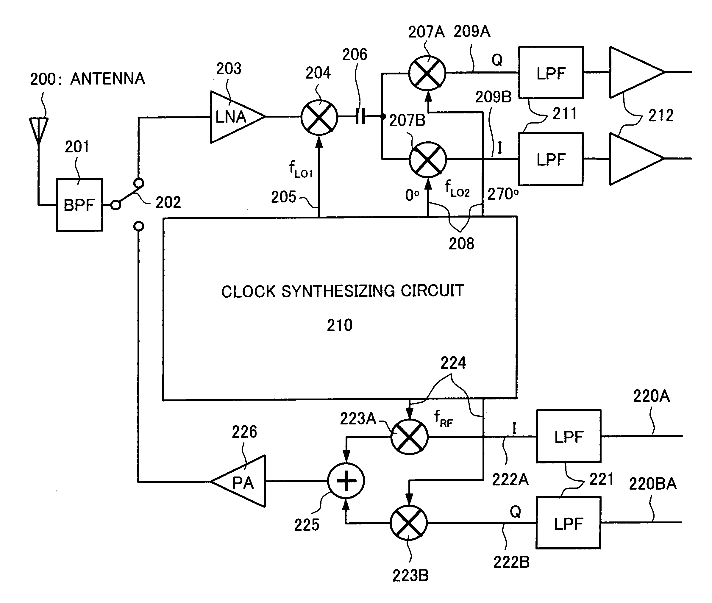
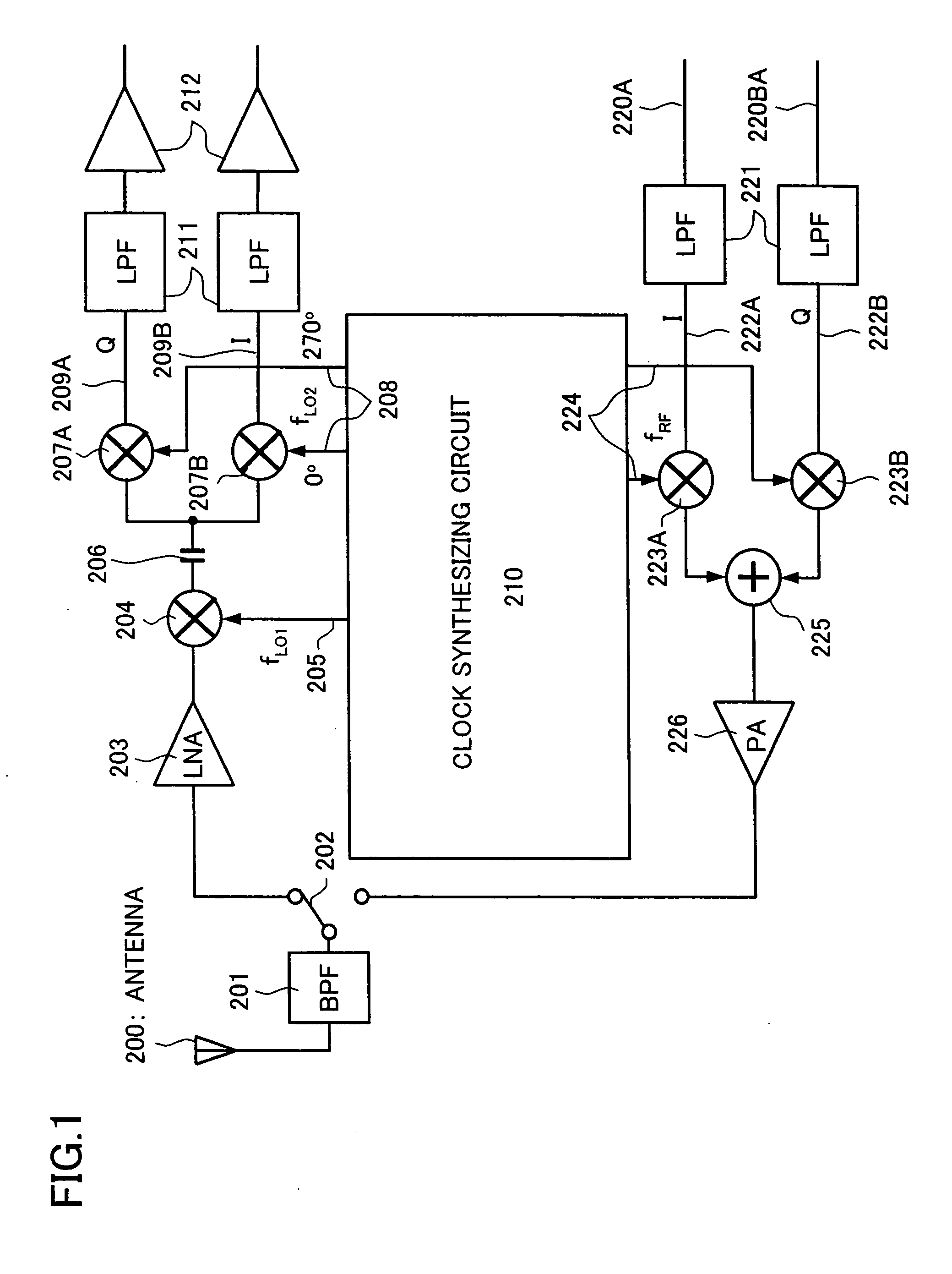
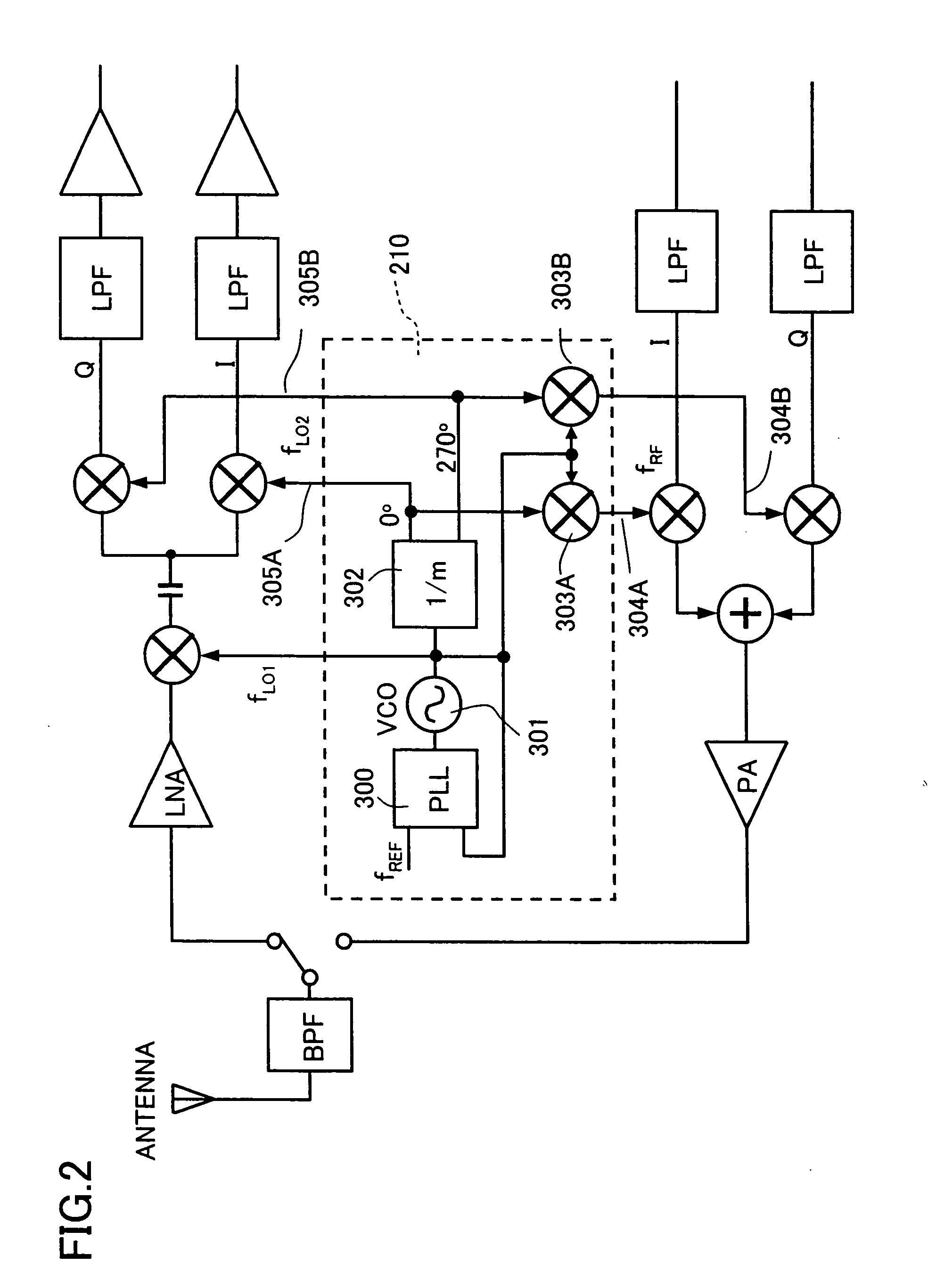
[0076] The present invention relates to an analog signal processing section of an IC-chipped transceiver (radio frequency transceiver) that is used in a wireless communication system using a radio frequency of 1 GHz or greater. The wireless communication system is applicable to (i) a mobile communication system such as a mobile phone or a PHS (personal handyphone system), (ii) a wireless LAN (local area network) which is compliant with the IEEE 802.11 standard, or the like.

[0077] In a transceiver of the best mode for carrying out the present invention, radio frequency modulation (transmitting) and radio frequency demodulation (receiving) are carried out with respect to a base-band signal. The feature of the present transceiver resides in how the radio frequency modulation and radio frequency demodulation are carried out. An object of the present invention is to downsize the transceiver so that the function of the transceiver is incorporated in an IC chip, and the IC chip is mounted...


PUM


Abstract

A frequency conversion circuit of the present invention includes: (i) a first mixer for mixing the radio frequency signal having a frequency fRF with a first oscillation signal having a frequency fLO1 so that the radio frequency signal is downconverted into an intermediate frequency signal; and (ii) a second mixer for mixing the intermediate frequency signal sent from the first mixer with two local oscillation signals so that the intermediate frequency signal is downconverted into two base-band signals having different phases. The second local oscillation signals have phases of 0° and 270°, respectively. These frequencies satisfies: fLO1=k×fRF(k>1) fLO2=fLO1 / m, (m>1) k=m / (m−1). This arrangement ensures (i) a small frequency conversion circuit that can be mounted on an integrated circuit, (ii) a radio frequency receiver including the frequency conversion circuit, and (iii) a radio frequency transceiver including the radio frequency receiver.

Description

[0001] This Nonprovisional application claims priority under 35 U.S.C. § 119(a) on Patent Application No. 2003 / 372535 filed in Japan on Oct. 31, 2003, the entire contents of which are hereby incorporated by reference.FIELD OF THE INVENTION [0002] The present invention relates to a radio frequency (RF) receiver and a radio frequency transceiver (i) that can extract, with the use of a quadrature mixer, a signal encoded based on an in-phase signal and a quadrature signal, and (ii) that are applicable to a mobile communication system such as a mobile phone, a PHS (Personal Handyphone System), or the like, and are also applicable to a wireless data communication system, which is compliant with the IEEE 802.11x standard, such as a wireless local area network (LAN) communication system, and further relates to a frequency conversion circuit for suitably use in the radio frequency (RF) receiver and the radio frequency transceiver. BACKGROUND OF THE INVENTION [0003]FIG. 10 illustrates a typic...

Claims


Application Information

Patent Timeline
Patent Type & Authority Applications(United States)
IPC IPC(8): H03D7/00H03D7/14H03D7/18H03K9/00H04B1/16H04B1/26H04B1/40
CPCH03D7/1441H04B1/408H03D2200/0084H03D7/1466H03D7/165H03D7/1458H04B1/40
Inventor ADAN, ALBERTO O.KAMIYA, SHINJI
Owner SHARP KK
Why Eureka
Try Eureka