Silicon chip carrier with conductive through-vias and method for fabricating same

Inactive Publication Date: 2005-06-09
GLOBALFOUNDRIES INC
View PDF8 Cites 377 Cited by
  • Summary
  • Abstract
  • Description
  • Claims
  • Application Information

AI Technical Summary

Benefits of technology

[0015] The foregoing and other objects are realized by the present invention which provides a carrier structure and method for fabricating a carrier structure having through-vias which are filled with a composite conductive material having a coefficient of thermal expansion which closely matches that of the substrate and having a modulus value which matches or is less than that of the substrate. The composite conductive material may be a conducting metal, a conducting metal ceramic, a conducting mixture of metals and ceramics, or a metal with a sealed void.
[0016] One embodiment of the invention includes a structure and method for fabricating a carrier structure having through-vias comprising concentric via fill a

Problems solved by technology

Problems have arisen in carriers of the prior art due to limitations in materials, deposition methods, control of dimensional tolerances, and mechanical stresses encountered during processing of the materials.
Filling such high aspect ratio vias is challenging.
However, the hydrodynamics, the ionic concentrations, and the diffusivities limit the filling of deep blind holes.
(ECTC 2002) did extensive plating optimization and were still not able to eliminate voids in vias of only 70 μm deep.
Methods for filling large blind holes which are to be opened later break down or become impractical at such dimensions.
The Black method provides adequate fill of the through-vias (for some of the listed materials); however, given the materials used, the resulting structure will experience the mechanical failures described below with reference to Table 1.
Gaul utilizes materials that are more closely thermally matched, namely W and poly-Si, but would not have practical deposition methods for multi-10's of μm and would have vastly differing values for modulus.
It is also to be noted that incorporation of embedded components into present carriers is difficult due to processing limitations, such as high temperature sintering conditions for ceramic carriers, as well as limitations with embedded component material systems.
At the above-stated diameters, most metals which are commonly used for integrated circuit interconnect vias generate unacceptable stress levels on the carrier layer material (e.g., Si or glass) due to thermal expansion mismatch.
In addition, t

Method used


Image

  • Silicon chip carrier with conductive through-vias and method for fabricating same
  • Silicon chip carrier with conductive through-vias and method for fabricating same
  • Silicon chip carrier with conductive through-vias and method for fabricating same

Examples


second embodiment

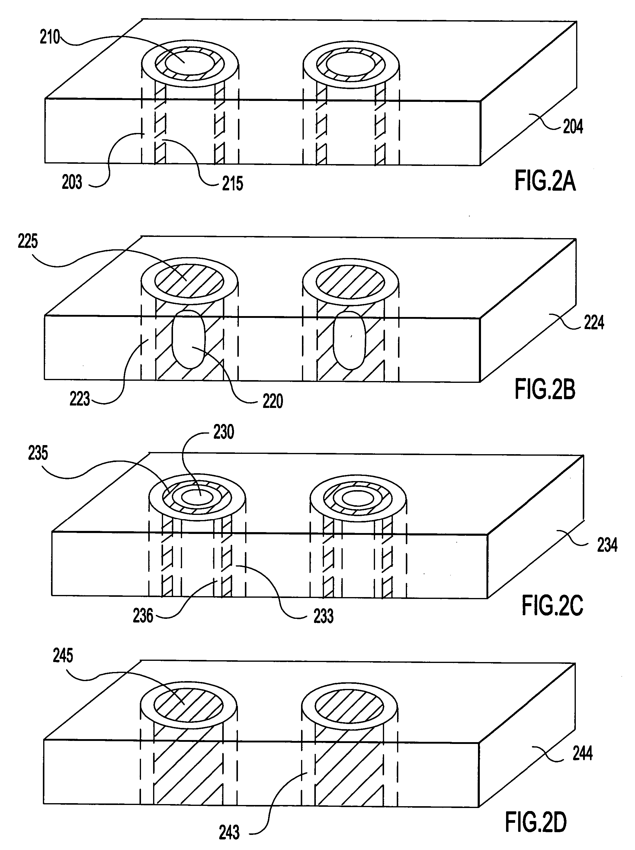
[0042]FIG. 5 is a flow chart of a representative process flow for fabricating a carrier with through-vias, as shown in FIG. 2B, in accordance with the present invention. At step 500, blind vias are etched into the substrate, as above, to a depth which is slightly greater than the desired depth of the through-vias in the finished product. At step 502, the sidewalls of the blind vias are insulated (as above), preferably by oxidizing silicon to form a thin layer of SiO2 or PECVD oxide or nitride or both. An annular fill is conducted at step 504 for provide metal (e.g., PVD TaN / Ta / Cu plus plated Cu to thickness ˜{fraction (1 / 10)} to ˜⅕ of the via diameter) along the exposed insulated surfaces of the blind via. The top of the via is then capped with metal by either an overfilling, burnishing, or similar technique. The void in the center of the via will contain the ambient of the capping process, typically N2 or a vacuum. Overfilling is achieved by a PVD, CVD, evaporation, or sputtering p...

third embodiment

[0045]FIG. 7 is a flow chart of a representative process flow for fabricating a carrier with through-vias, as shown in FIG. 2C, in accordance with the present invention. At step 700, blind vias are etched into the substrate to a depth which is the desired depth of the through-vias in the finished product. The vias are etched in a pattern whereby each is an annular via of thickness ˜{fraction (1 / 10)} to ˜⅕ of the via diameter etched about a post of substrate material which will remain as the core of the via. At step 702, the sidewalls of the blind vias are insulated, preferably by oxidizing silicon to form a thin layer of SiO2 (see above) on both the outer sidewalls and the post sidewalls. The annular vias are then overfilled with the desired conductive material at step 704. Thereafter, the top of the structure is planarized at step 708 to remove excess metal at the top surface and to expose the substrate between the annular metal rings of the vias. IC circuits or components may be f...


PUM


Abstract

A carrier structure and method for fabricating a carrier structure with through-vias each having a conductive structure with an effective coefficient of thermal expansion which is less than or closely matched to that of the substrate, and having an effective elastic modulus value which is less than or closely matches that of the substrate. The conductive structure may include concentric via fill areas having differing materials disposed concentrically therein, a core of the substrate material surrounded by an annular ring of conductive material, a core of CTE-matched non-conductive material surrounded by an annular ring of conductive material, a conductive via having an inner void with low CTE, or a full fill of a conductive composite material such as a metal-ceramic paste which has been sintered or fused.

Description

FIELD OF THE INVENTION [0001] The invention relates generally to a carrier for mounting and packaging multiple integrated circuit chips; and, more particularly, to a self-supporting semiconductor or insulator carrier substrate with conductive through-vias. BACKGROUND OF THE INVENTION [0002] A carrier for integrated circuit devices is typically fabricated of semiconductor, glass, or glass-ceramic material as a freestanding substrate, chip or wafer having conductive through-vias. The through-vias are exposed on the top and underside of the carrier and are insulated from each other. Multiple levels of carrier material with metallic or semi-metallic vias are often required to obtain the necessary conductive paths between chips and other devices mounted with respect to the carrier. The carrier having through-vias provides chip input / output terminals (I / O), with the chips typically mounted in the “flip chip” manner, and other device I / O through the carrier from the surface at which the ch...

Claims


Application Information

Patent Timeline
IPC IPC(8): H01L21/48H01L21/768H01L23/498
CPCH01L21/486H01L21/76898H01L2924/10253H01L23/49827H01L23/49883H01L2224/16H01L2924/01004H01L2924/01078H01L2924/01079H01L2924/09701H01L2924/15311H01L2924/3011H01L2924/3025H01L2924/01019H01L2924/01322H01L2924/00
Inventor EDELSTEIN, DANIEL CHARLESANDRY, PAUL STEPHENBUCHWALTER, LEENA PAIVIKKICASEY, JON ALFREDGOMA, SHERIF A.HORTON, RAYMOND R.HOUGHAM, GARETH GEOFFREYLANE, MICHAEL WAYNELIU, XIAO HUPATEL, CHIRAG SURYAKANTSPROGIS, EDMUND JURISSTEEN, MICHELLE LEIGHSUNDLOF, BRIAN RICHARDTSANG, CORNELIA K.WALKER, GEORGE FREDERICK
Owner GLOBALFOUNDRIES INC
Why Eureka
Try Eureka