Rf system concept for vehicular radar having several beams

a vehicular radar and beam technology, applied in the direction of reradiation, transmission, printed circuit aspects, etc., can solve the problems of unfavorable mass market application, and inability to implement a simple, efficient transceiver that is to be usable in a mass market environment, so as to facilitate coupling to the pcb and simplify the mounting of components

Inactive Publication Date: 2005-06-09
GROENEVELD TRANSPORT EFFICIENCY
View PDF33 Cites 15 Cited by
  • Summary
  • Abstract
  • Description
  • Claims
  • Application Information

AI Technical Summary

Benefits of technology

[0014] The active components of the modules most preferably use microwave integrated circuit (MIC) technology to simplify mounting of the components on their respective dielectric substrates. An optional mm wave short for each microstrip-wav

Problems solved by technology

Because of their use in vehicles, the transceivers have to comply with a number of constraints, which taken together make it extremely difficult to implement a simple, efficient transceiver that is to be usable in a mass market environment.
Some of the constraints are inherent to operating with millimeter waves, which are typically transmitted in waveguides, microstrips, or by short wire bonds between components.
The problems generated by the millimeter (mm) wavelengths include requirements for close tolerances for mm wave structur

Method used


Image

  • Rf system concept for vehicular radar having several beams
  • Rf system concept for vehicular radar having several beams
  • Rf system concept for vehicular radar having several beams

Examples


Embodiment Construction

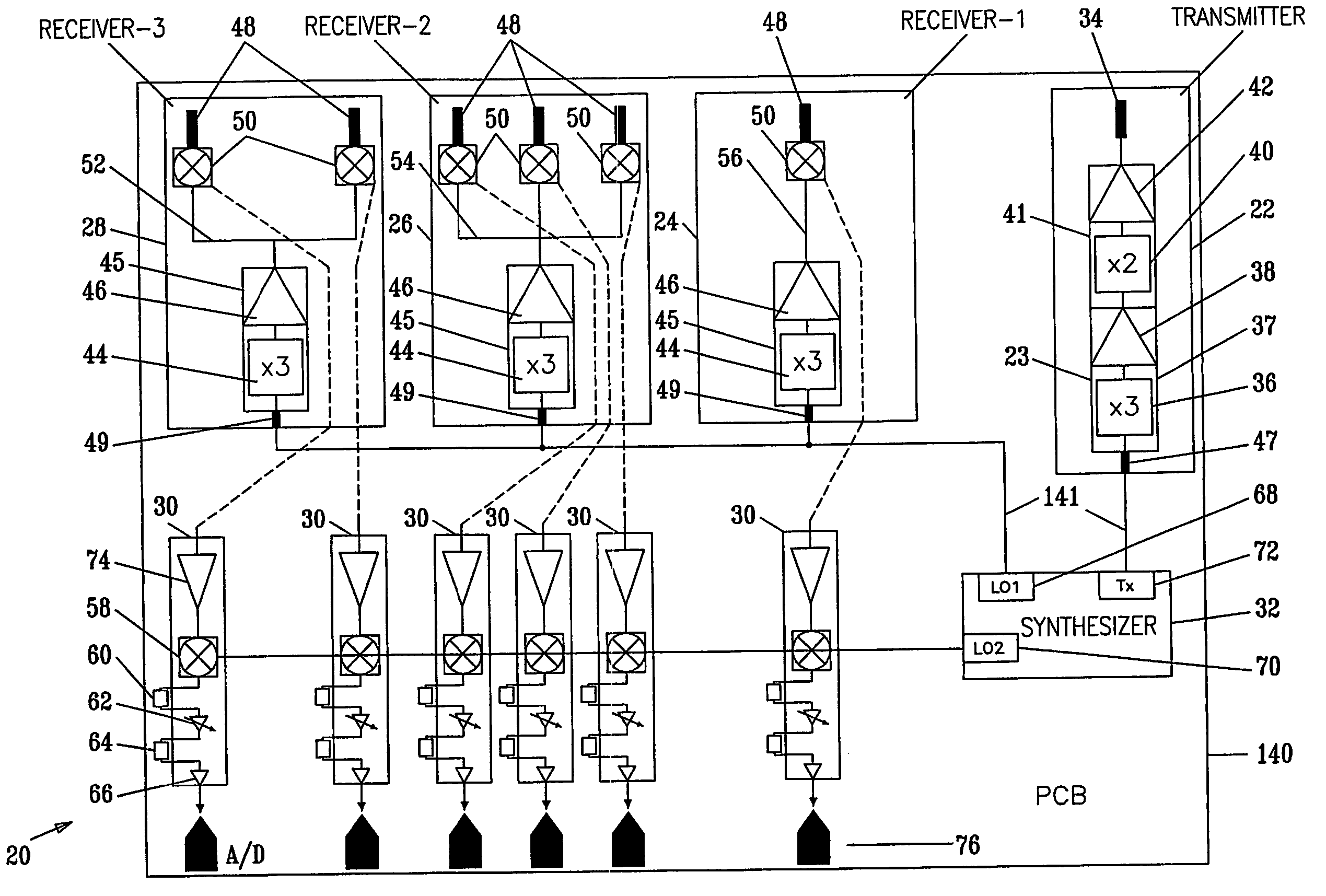
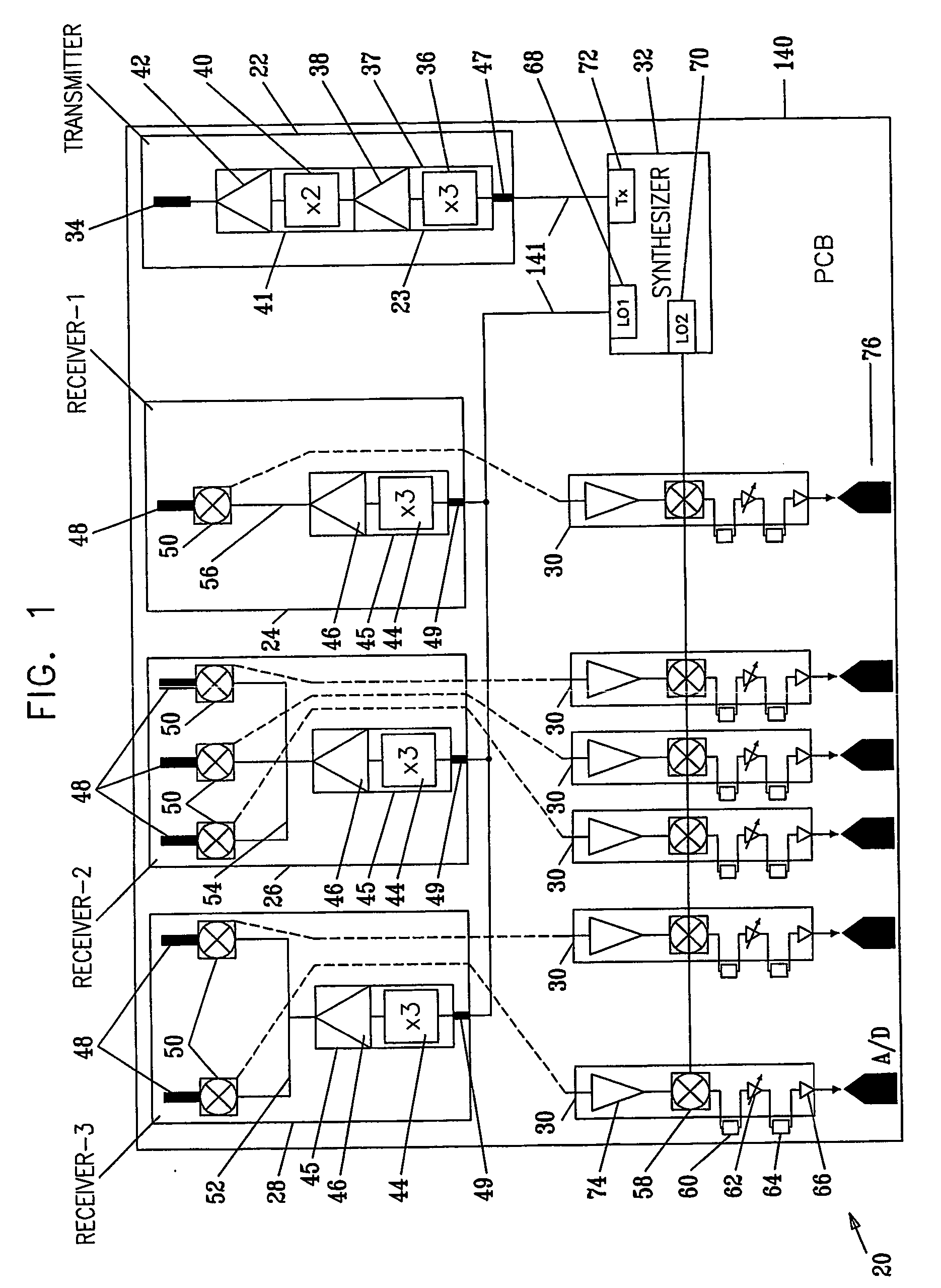
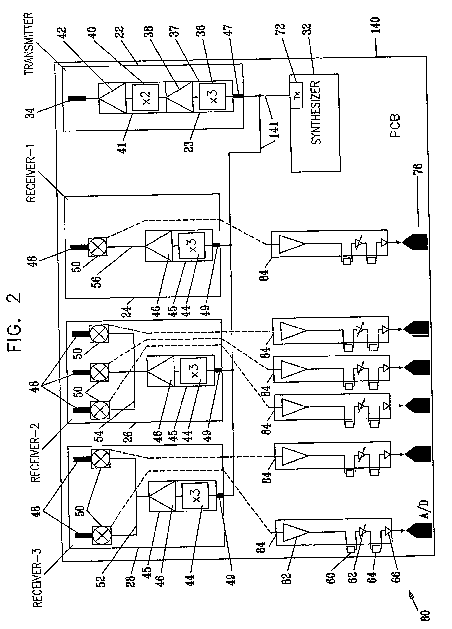
[0069] Reference is now made to FIG. 1, which is a schematic block diagram of a millimeter wave multiple beam transceiver 20, according to a preferred embodiment of the present invention. Transceiver 20 comprises a transmitter module 22 which generates millimeter (mm) waves, at frequencies of the order of W-band, the mm waves being coupled to a transmitting antenna via a mm wave microstrip-waveguide transition 34, which acts as a mm wave output port. Herein, millimeter (mm) waves are assumed to be waves having frequencies of the order of W-band. In order to generate its mm waves, transmitter 22 receives a low frequency (LF) reference signal, at frequencies of the order of 12 GHz, from a frequency synthesizer 32. The LF signal is received via a microstrip-microstrip transition 47, which acts as an LF inlet port to transmitter module 22.

[0070] Transmitter 22 comprises a x3 frequency multiplier 36, a first amplifier 38, a x2 frequency multiplier 40, and a second amplifier 42, connecte...


PUM


Abstract

ABSTRACTA transceiver (20) for a millimeter wave signal, consisting of a PCB (140) having PCB microstrip lines (141) and PCB waveguide apertures (159), and one or more transmitter modules (22) and one or more receiver modules (24, 26, 28) mounted on the PCB. Each module has a single microstrip-waveguide transition (34, 48) and a microstrip-microstrip transition (47, 49). The microstrip-waveguide transition of each module couples to one of the PCB waveguide apertures via a PCB-module waveguide-waveguide transition (167). The microstrip-microstrip transition of each module couples to one of the PCB microstrip lines via a PCB-module microstrip-microstrip transition (165). The PCB-module transitions are low tolerance, facilitating implementation of the transceiver.

Description

CROSS-REFERENCE TO RELATED APPLICATION [0001] This application claims the benefit of U.S. Provisional Patent Application No. 60 / 374,227, filed Apr. 19, 2002, which is incorporated herein by reference.FIELD OF THE INVENTION [0002] The present invention relates generally to transceiver design, and specifically to design of transceivers for millimeter wavelength waves for vehicular radars. BACKGROUND OF THE INVENTION [0003] Radar transceivers operating at millimeter wavelengths have been in use for some time on vehicles, where they are installed to provide such features as warnings of obstacles that may not be visible to a driver of the vehicle, or for autonomous cruise control (ACC). Because of their use in vehicles, the transceivers have to comply with a number of constraints, which taken together make it extremely difficult to implement a simple, efficient transceiver that is to be usable in a mass market environment. [0004] Some of the constraints are inherent to operating with mil...

Claims


Application Information

Patent Timeline
IPC IPC(8): G01S7/03H01P5/107H01Q1/32H01Q9/30H01Q9/40H01Q21/00H01Q21/08H01Q25/00H05K1/02H05K1/14
CPCH01P5/107H01Q1/3233H01Q9/30H01Q9/40H01Q21/0025H05K2201/09618H01Q25/00H05K1/0219H05K1/0243H05K1/141H01Q21/08
Inventor SHMUEL, AMIR
Owner GROENEVELD TRANSPORT EFFICIENCY
Why Eureka
Try Eureka