
Virtual spherical anode computed tomography

a virtual spherical anode and computed tomography technology, applied in tomography, x-ray tube targets, convertors, etc., can solve the problems of preventing the use of tomography, affecting so as to improve the volumetric acquisition of ct data, improve the accuracy of tomography, and improve the effect of flexibility in selecting projections

Inactive Publication Date: 2005-06-09
WISCONSIN ALUMNI RES FOUND
View PDF21 Cites 62 Cited by
  • Summary
  • Abstract
  • Description
  • Claims
  • Application Information

AI Technical Summary

Benefits of technology

[0013] The present invention provides improved volumetric acquisition of CT data by breaking free from the planar acquisition pattern to acquire sequential projections both aligned with and oblique to the slice plane. K-space is filled, not on a plane-by-plane basis, like spokes on wheels but in a three-dimensional starburst pattern. This out-of-plane acquisition provides a number of benefits including the ability to collect missing k-space data caused by beam divergence without patient translation, increased flexibility in selecting projection angle to minimize or measure tissue motion, and the ability to rapidly collect sparse projection sets for large volume imaging on a real time basis without being constrained to a helical or orbital acquisition sequence.
[0015] Unlike magnetic resonance imaging, however, in which different projection angles may be obtained simply by changing the gradient fields, in x-ray CT, an actual x-ray beam at different three-dimensional angles must be obtained. The present invention addresses this problem with a large-area x-ray emitter that approximates a spherical source. A broad-area detector opposing the anode allows full utilization of the data obtained both in and out of slice plane. Undersampling and interleaving can be used to further decrease sampling time.

Problems solved by technology

Reconstructions using too few projections or a limited number of gantry angles may produce images with “artifacts”, typically streaks, that mar the tomographic image.
The time required to collect projection data over a volume using conventional fan-beam tomography can be substantial and may preclude the use of tomography in situations where large volumes are to be monitored in real-time (for example, in contrast studies) or where there is unavoidable patient or organ motion during the acquisition time.
While these systems provide for more rapid data acquisition, they are fundamentally limited by the rotational speed of the gantry.

Method used


Image

  • Virtual spherical anode computed tomography
  • Virtual spherical anode computed tomography
  • Virtual spherical anode computed tomography

Examples


Embodiment Construction

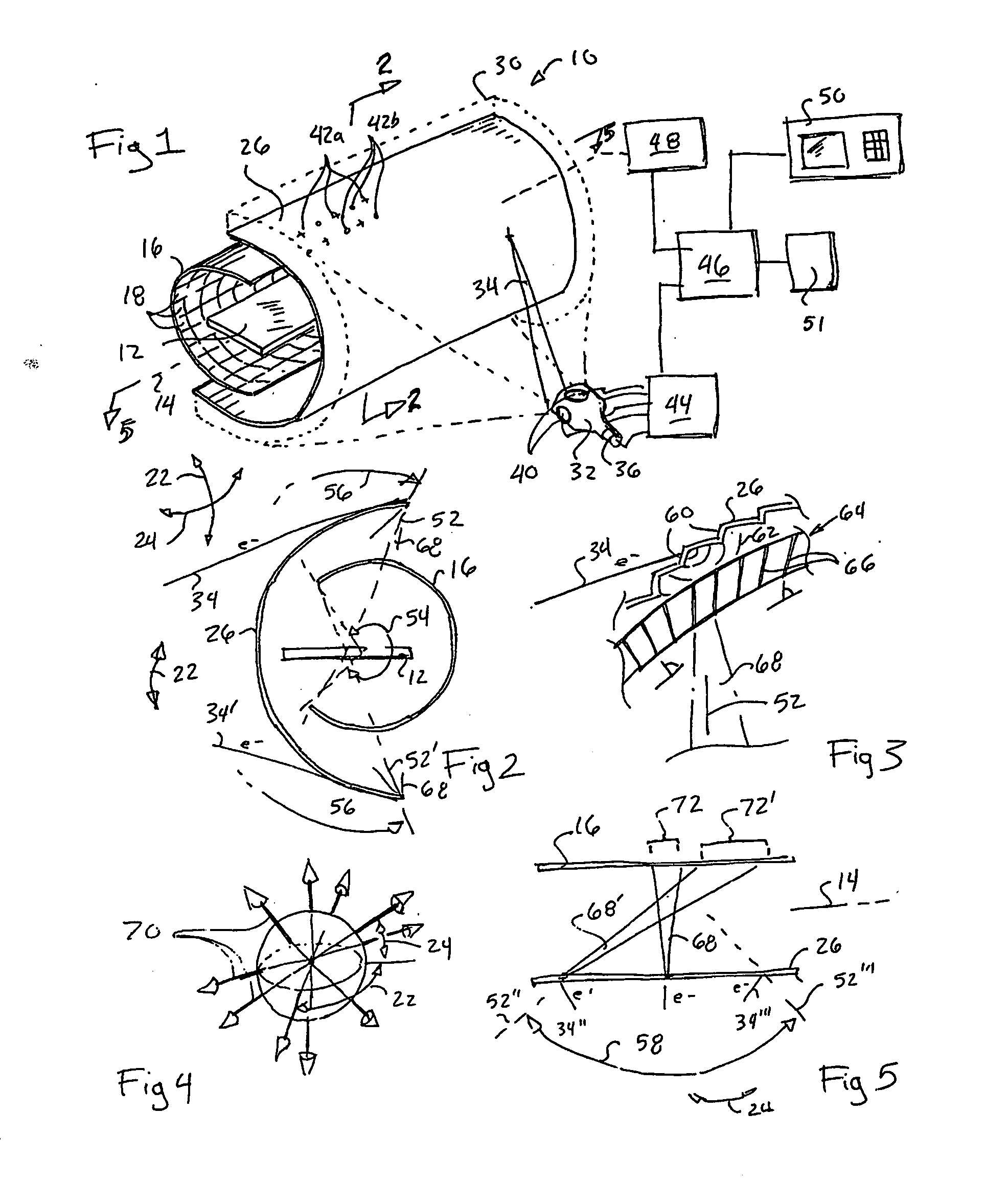
[0046] Referring to FIG. 1, a CT system 10 suitable for use with the present invention provides a horizontal patient table 12 extending generally along a longitudinal axis 14 on which a patient (not shown) may be supported in a supine position.

[0047] A detector array 16 is curved about the patient table 12 following the curved wall of a hemi-cylinder whose axis is aligned with the longitudinal axis 14. The inner surface of the detector array 16 supports a series of detector elements 18 arranged in rows and columns facing the patient table 12. The detector elements 18 may thus receive x-rays transmitted through the patient on the patient table 12 from a variety of different latitudinal angles 22 being generally those in a vertical plane or longitudinal angles 24 being generally those in a horizontal plane. The detector elements 18 may be conventional scintillation type x-ray detectors but may also include ionization type or CZT detectors or other such detectors well-known in the art...


PUM

PropertyMeasurementUnit
longitudinal anglesaaaaaaaaaa
angleaaaaaaaaaa

Abstract

An x-ray computed tomography system uses a broad area x-ray emitter and detector to allow both in plane and out of plane x-ray projections not restrained to spiral or helical scans.

Description

CROSS-REFERENCE TO RELATED APPLICATIONS [0001] This application is based on provisional application 60 / 341,560 filed Dec. 14, 2001 and entitled “Virtual Spherical Anode Computer Tomography”.STATEMENT REGARDING FEDERALLY SPONSORED RESEARCH OR DEVELOPMENT [0002] This invention was made with United States government support awarded by the following agencies: NIH HL62425. The United States has certain rights in this invention.BACKGROUND OF THE INVENTION [0003] The present invention relates to x-ray computed tomography (CT) and specifically to a CT system and method providing high-speed data acquisition. [0004] Conventional x-ray computed tomography may employ an x-ray source collimated to produce a narrow fan-shaped beam directed along the transverse plane through a patient to be received by linear multi-element detector array. [0005] The x-ray source and detector array may be mounted on a gantry to be rotated about a patient to obtain “projections” measuring x-ray attenuation at the di...

Claims


Application Information

Patent Timeline
Patent Type & Authority Applications(United States)
IPC IPC(8): A61B6/03G01N23/04H01J35/30
CPCA61B6/032A61B6/4028G01N23/046G01N2223/612H01J2235/086A61B6/027G01N2223/419H01J35/30
Inventor MISTRETTA, CHARLES A.MACKIE, THOMAS R.
Owner WISCONSIN ALUMNI RES FOUND
Learn More