
SMD type biased condenser microphone

Inactive Publication Date: 2005-06-09
BSE CO LTD
View PDF3 Cites 15 Cited by
  • Summary
  • Abstract
  • Description
  • Claims
  • Application Information

AI Technical Summary

Benefits of technology

[0010] An object of the present invention is to provide an SMD type biased condenser microphone that can improve compatibility with a conventional ECM by including a two-terminal type device using a decoupling capacitor, and solve the directional problem of the circular condenser microphone in the surface mounting process, and also form the electrostatic field by applying a voltage from the outside so as to be capable of maintaining a constant electric field even after reflow work thereby preventing loss of sensitivity.
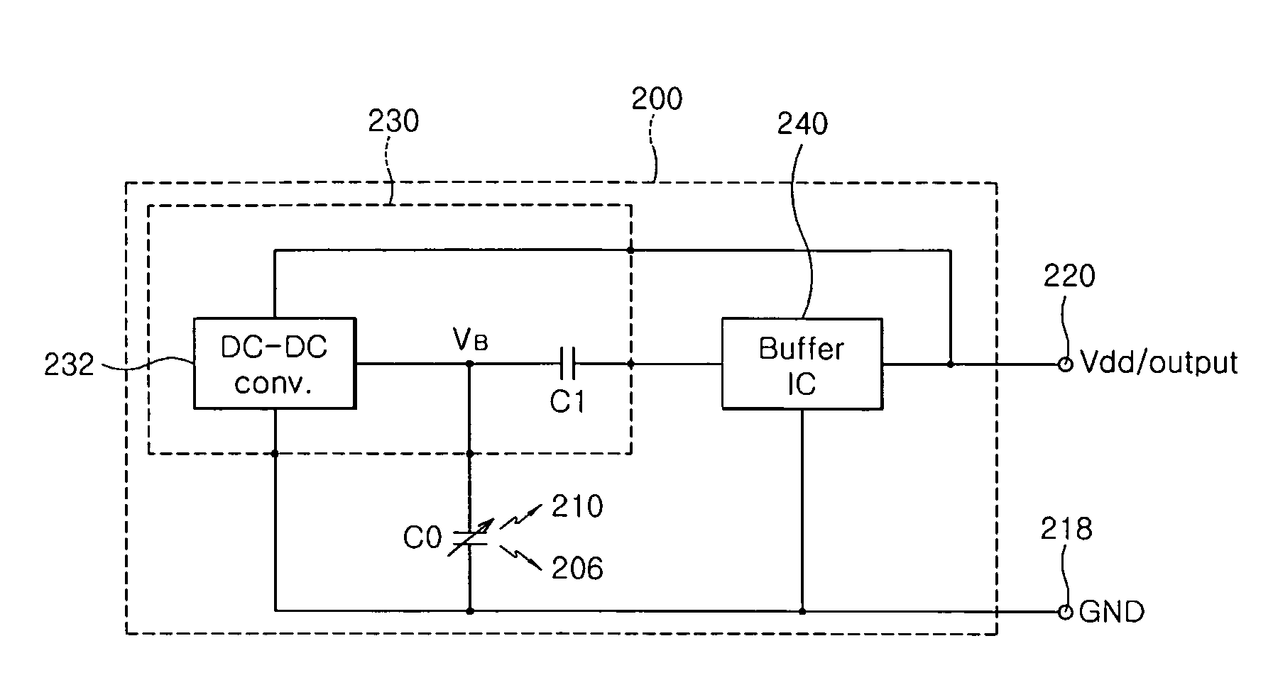
[0012] To achieve these objects and other advantages and in accordance with the purpose of the invention, as embodied and broadly described herein, there is provided an SMD type biased condenser microphone, comprising a grounding terminal for connecting with an external circuit; a diaphragm / backplate set one end of which is connected to the grounding terminal, for varying a capacity according to an intensity of sound pressure and converting sound into an electric signal; a DC-DC converter for providing a bias voltage so as to form an electrostatic field at one side of the diaphragm / backplate set; a buffer IC for amplifying the electric signal from the diaphragm / backplate set; and a decoupling capacitor for preventing the bias voltage output from the DC-DC converter from being directly applied to the buffer IC and transferring the electric signal from the diaphragm / backplate set to the buffer IC.
[0013] Therefore, the present invention can improve compatibility with a conventional ECM, and solve the directional problem of the circular condenser microphone in the surface mounting process, and also form the electrostatic field by applying a voltage from the outside so as to be capable of maintaining a constant electric field even after reflow work thereby preventing loss of sensitivity.

Problems solved by technology

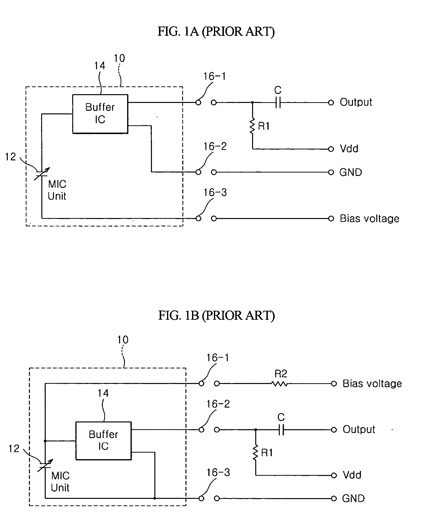
However, since the conventional biased condenser microphone is provided with at least three terminals such as the bias terminal, the power and output terminal and the grounding terminal so as to interface with the outside, there is a problem that a direction of the circular condenser microphone should be checked upon a surface mounting process.
Further, since a separate voltage device for supplying the bias voltage has to be provided to the outside of the microphone, it is difficult to miniaturize the microphone.
Furthermore, since it has poor compatibility with an electret condenser microphone (ECM), which is generally used for connection with an external circuit, there is another problem that includes providing a printed circuit board (PCB), which has to be separately designed.

Method used


Image

  • SMD type biased condenser microphone
  • SMD type biased condenser microphone
  • SMD type biased condenser microphone

Examples


first embodiment

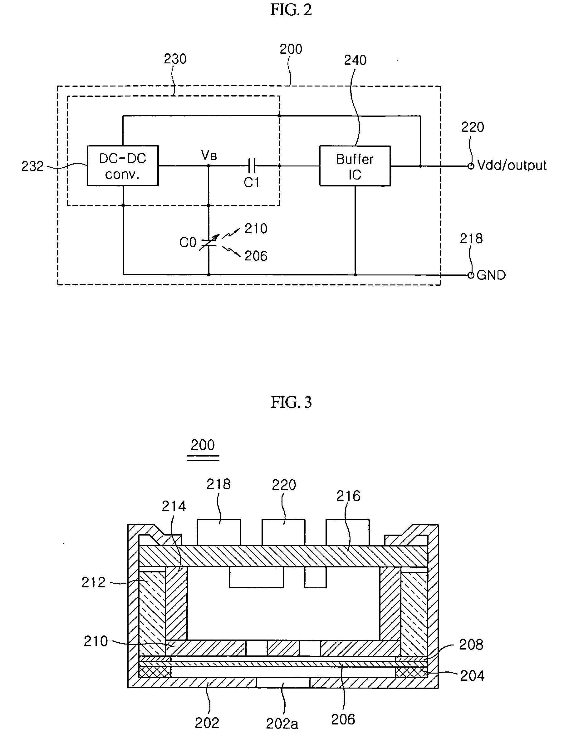
[0026]FIG. 2 is a circuit diagram of an SMD type condenser microphone according to a first embodiment of the present invention, and FIG. 3 is a cross-sectional view of the SMD type condenser microphone according to the first embodiment of the present invention.

[0027] In the equivalent circuit according to a first embodiment of the present invention, as shown in FIG. 2, a diaphragm 206 and a backplate 210 are represented as a single variable condenser C0 so that the diaphragm 206 is connected to a grounding portion GND and the backplate 210 is connected to a DC-DC converter 232. A decoupling capacitor C1 is connected between the DC-DC converter 232 and a buffer IC 240. Herein, a voltage pump IC 230 is comprised of the DC-DC converter 232 and the decoupling capacitor C1, and the buffer IC 240 may include an FET, an amplifier or an analog-digital converter.

[0028] Meanwhile, in an internal PCB circuitry, if necessary, a circuit for connecting capacitors or capacitors, resistors, etc.,...

second embodiment

[0035]FIG. 5 is a circuit diagram of an SMD type condenser microphone 500 according to a second embodiment of the present invention, and FIG. 6 is a cross-sectional view of the SMD type condenser microphone 500 according to the second embodiment of the present invention.

[0036] In comparison with the first and second embodiments of the present invention, since a structure of the second embodiment is entirely similar to that of the first embodiment except for relocation of the backplate 210 and the diaphragm 206, the description of the same or similar parts will be omitted.

[0037] Referring to FIGS. 5 and 6, in the circuit of the second embodiment compared with the equivalent circuit of the first embodiment, the variable condenser CO is equivalent to the backplate 210 and the diaphragm 206, and the backplate 210 is connected to the grounding portion, and the diaphragm 206 is connected to the DC-DC converter 232.

[0038] That is, in the second embodiment, the driving voltage Vdd is app...


PUM


Abstract

A surface mounted device (SMD) type biased condenser microphone includes two terminals for a surface mounting process. The SMD type biased condenser microphone includes a grounding terminal for connecting with an external circuit, a diaphragm / backplate set, one end of which is connected to the grounding terminal, for varying a capacity according to an intensity of sound pressure and converting sound into an electric signal, a DC-DC converter for providing a bias voltage so as to form an electrostatic field at one side of the diaphragm / backplate set, a buffer IC for amplifying the electric signal from the diaphragm / backplate set, and a decoupling capacitor for preventing the bias voltage output from the DC-DC converter from being directly applied to the buffer IC and transferring the electric signal from the diaphragm / backplate set to the buffer IC.

Description

BACKGROUND OF THE INVENTION [0001] 1. Field of the Invention [0002] The present invention relates to a biased condenser microphone, and more particularly, to an SMD (surface mounting device) type biased condenser microphone having two connecting terminals for a surface mounting. [0003] 2. Description of the Related Art [0004] Generally, a condenser microphone includes a set of diaphragm and backplate provided with a capacitor (C), the capacitance of which is changed depending on a voltage bias factor and a sound pressure, and a junction field effect transistor (JFET) for buffering an output signal. [0005] As an example of such a condenser microphone, there is a biased condenser microphone in which a bias voltage is supplied from the outside to form an electrostatic field between the diaphragm and the backplate. [0006]FIG. 1A is an equivalent circuit diagram of a conventional biased condenser microphone. A microphone capsule 10 including a buffer IC 14 and a variable condenser 12 in ...

Claims


Application Information

Patent Timeline
IPC IPC(8): H04R3/00H04R1/04H04R19/00H04R19/04
CPCH04R19/04H04R1/06
Inventor SONG, CHUNG DAMCHUNG, EEK JOOHO, HYUN
Owner BSE CO LTD
Learn More