Process for removing thermal barrier coatings

a technology of thermal barrier coating and thermal barrier coating, which is applied in the direction of efficient propulsion technology, manufacturing tools, mechanical equipment, etc., can solve the problems of tbc debonding, laser induced damage, and prolonging the life of engine components

Inactive Publication Date: 2005-06-16
TURBOCOMBUSTOR TECH
View PDF37 Cites 29 Cited by
  • Summary
  • Abstract
  • Description
  • Claims
  • Application Information

AI Technical Summary

Benefits of technology

[0007] Briefly, the present invention provides a process which uses an air jet containing non-abrasive particulate media at a low pressure which selectively removes thermal barrier coatings from components without damaging the metallic substrate. This process selectively removes thermal barrier coatings from the cooling holes of components.

Problems solved by technology

Lowering the temperature of the metal substrate prolongs the life of the engine component.
The laser drilling process can manufacture the cooling holes by drilling through the component's metallic substrate and the TBC at the same time; however, laser induced damage occurs during this manufacturing process.
Microstructural damage is generated at the TBC interface with the metallic bond coat and metallic substrate which results in TBC debonding and subsequent ceramic insulation coating loss (spallation) which is detrimental to the metallic substrate due to the high heat loads which adversely affects part durability and service life.

Method used


Image

  • Process for removing thermal barrier coatings
  • Process for removing thermal barrier coatings

Examples


example

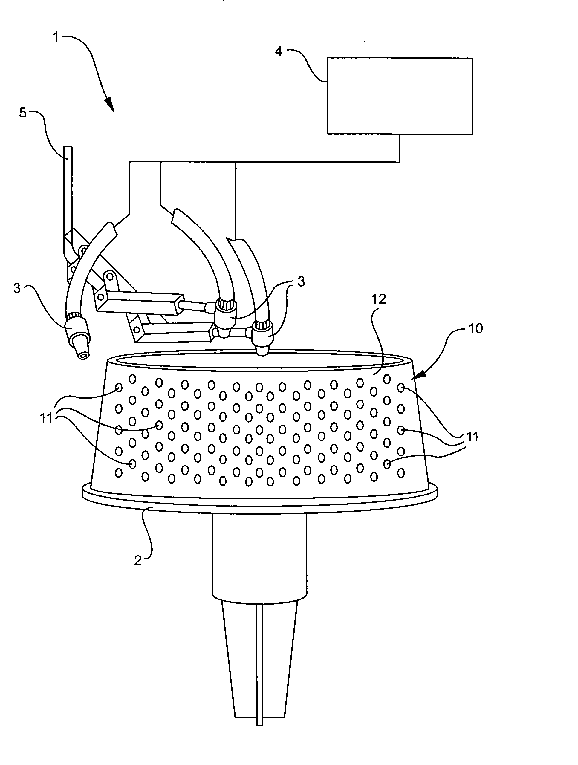
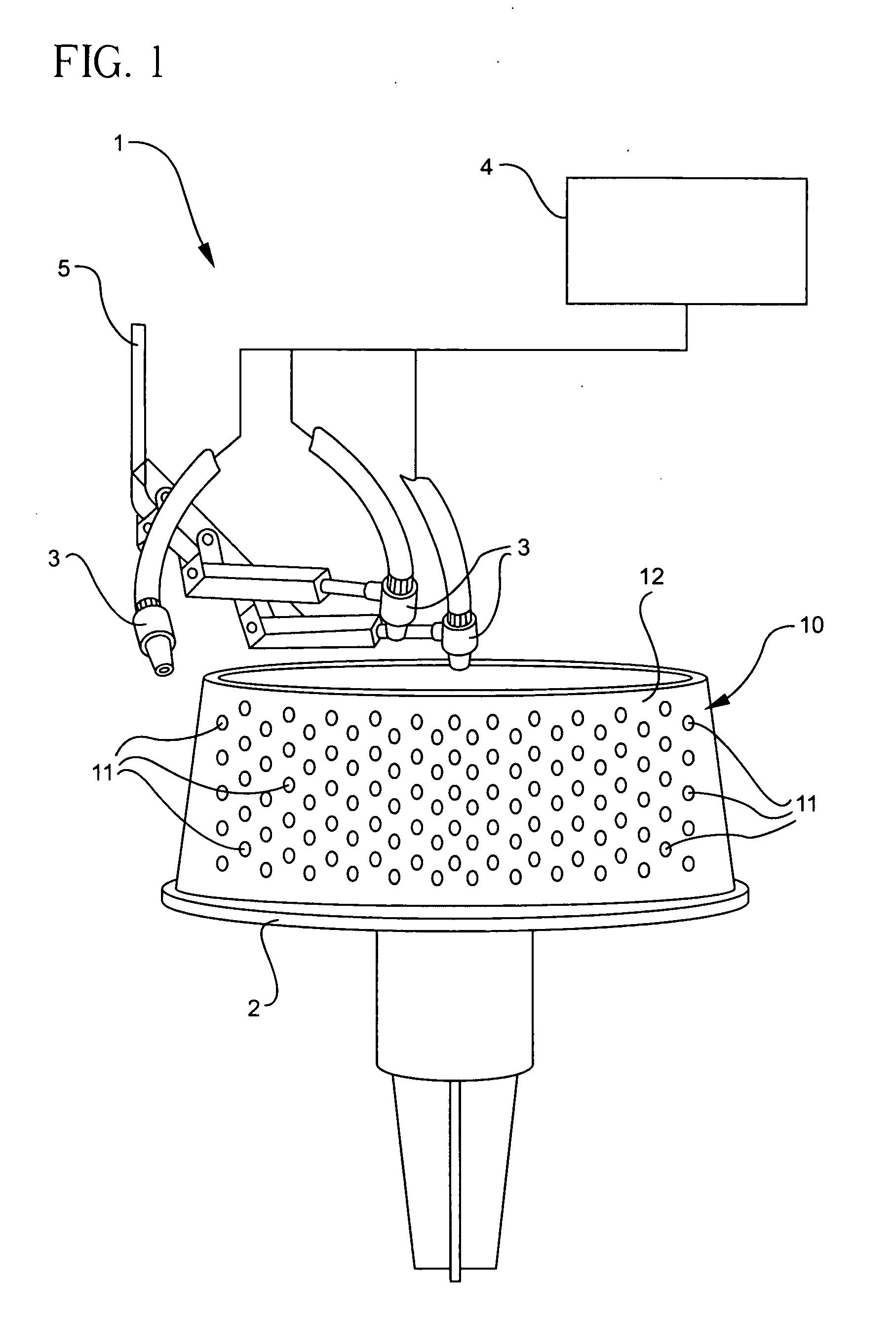
[0018] A jet engine hot section combustion chamber (manufactured from a cobalt or nickel based superalloy material) is manufactured having air cooling holes laser drilled therein. The gas path (hot side) surface of the component is first coated with a metallic bond coat which is predominantly nickel and containing chromium, aluminum and yttria (or another reactive element). The metallic bond coat is applied by plasma spraying to a thickness which is typically about 0.005 to 0.008 inch (about 0.13 to 0.020 mm). After bond coat application, the air cooling holes are manufactured utilizing a laser drilling process to create the desired angle of incidence in order to achieve the required air flow cooling characteristics for the component. After laser drilling, the component is cleaned to remove any laser slag or displaced material resulting from the laser drilling process. After laser drilling and cleaning, an optional bond coat layer of the same material can be applied by the plasma sp...


PUM

PropertyMeasurementUnit
diameteraaaaaaaaaa
diameteraaaaaaaaaa
pressuresaaaaaaaaaa

Abstract

Briefly, the present invention provides a process which uses an air jet containing non-abrasive particulate media at a low pressure which selectively removes thermal barrier coatings from components without damaging the metallic substrate. This process selectively removes thermal barrier coatings from the cooling holes of components.

Description

BACKGROUND OF THE INVENTION [0001] The present invention relates generally to a process for removing thermal barrier coatings from metal components and more particularly to a method for removing a thermal barrier ceramic coating from the cooling holes of a gas turbine engine component, such as a combustor chamber liner. [0002] Gas turbine engines (aerospace and industrial) are designed such that their nickel and cobalt based superalloy components operate at temperatures very close to their melting points. Thermal barrier coatings (TBC) perform the important function of insulating components operating at elevated temperatures. Typical turbine components are combustion chamber (see combustion chamber 10 in FIG. 1), ducts, discharge nozzles, turbine blades and nozzle guide vanes. TBCs are characterized by their very low thermal conductivity, the coating bearing a large temperature gradient when exposed to heat flow. [0003] The most commonly applied TBC material is yttria stabilized zir...

Claims


Application Information

Patent Timeline
Patent Type & Authority Applications(United States)
IPC IPC(8): B23P6/00
CPCB23P6/002B23P2700/06C23C4/005Y10T29/4533Y10T29/49318Y10T29/49885Y10T29/49995Y10T29/49341Y10T29/455C23C4/01Y02T50/60
Inventor HANLEY, GARY LYNN
Owner TURBOCOMBUSTOR TECH
Why Eureka
Try Eureka