Hybrid cemented carbide composites

a cemented carbide and composite technology, applied in the field of hybrid cemented carbide composites, can solve the problems of increasing fracture toughness, increasing toughness generally accompanied by a decrease in wear resistance, and undergoing abrasive wear and thermal fatigu

Active Publication Date: 2005-06-16
KENNAMETAL INC
View PDF42 Cites 144 Cited by
  • Summary
  • Abstract
  • Description
  • Claims
  • Application Information

AI Technical Summary

Problems solved by technology

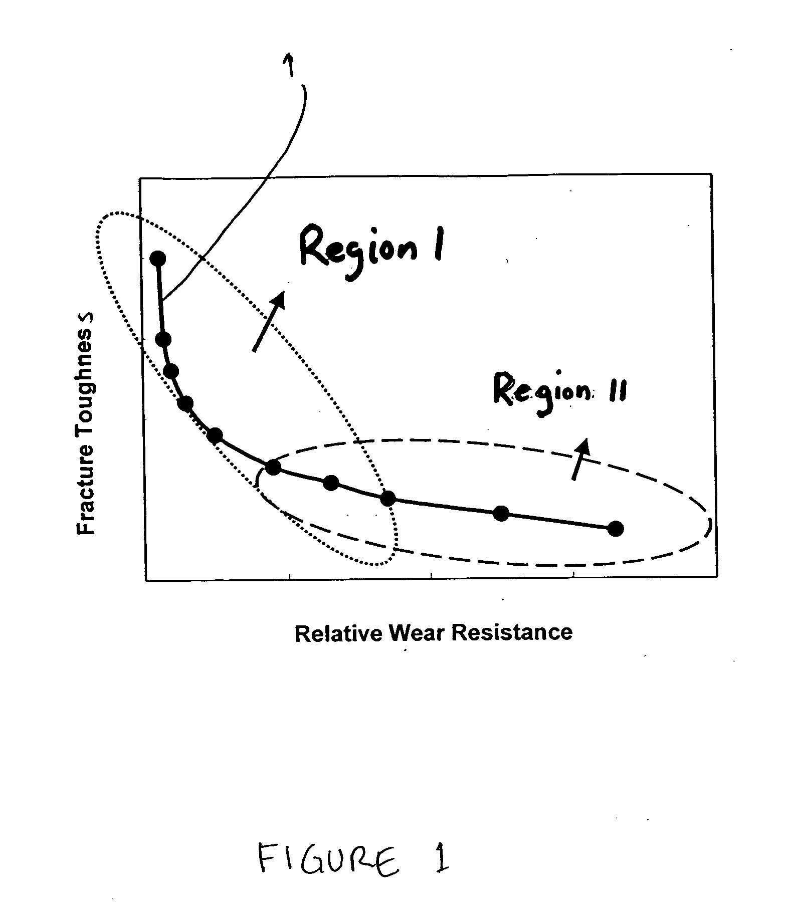
Generally, an increase in the average grain size of tungsten carbide and / or an increase in the volume fraction of the cobalt binder will result in an increase in fracture toughness.
However, this increase in toughness is generally accompanied by a decrease in wear resistance.
Grades based on coarse tungsten carbide grains find extensive use in applications where the material experiences shock and impact and also may undergo abrasive wear and thermal fatigue.
FIG. 1 indicates that even making small improvements in wear resistance of the cemented carbide grades in Region I using conventional techniques results in a large decrease in fracture toughness.
However, there are practical limits to the manufacture of the tungsten carbide grain sizes.
In addition, large tungsten carbide grains, because of their inherent brittle nature, tend to crack and fracture when subjected to abrasive wear.
Thus, while the rate of abrasive wear is essentially independent of tungsten carbide grain size below a certain size level, the observed rate of abrasive wear can dramatically increase when the tungsten carbide grain size exceeds a certain optimum size.
Therefore, while increasing the tungsten carbide grain size at any given cobalt content is one technique that may provide improved toughness at a given wear resistance level, the practical utility of this method is limited.
Improvements in properties are realized by this method, however, the unsintered granules of the cemented carbide grades collapse during the powder consolidation, typically by a powder pressing operation, resulting in a microstructure of the final material consisting of one cemented carbide grade intermeshed within the other grade.
This technique limits the ability to control the shape of the regions of either of the grades.
Due to the absence of any control of the microstructure in these composite cemented carbides, cracks once started may easily propagate through the continuous paths of the hard grade.
Thus, these composites tend to chip and break and the fracture toughness of the bulk composite is not significantly higher than the fracture toughness of the phase of the cemented carbide with the lowest fracture toughness, typically the hard phase.

Method used


Image

  • Hybrid cemented carbide composites
  • Hybrid cemented carbide composites
  • Hybrid cemented carbide composites

Examples


example 1

[0035] A hybrid cemented carbide was prepared by the method of the present invention. See FIG. 4B. In the embodiment of the hybrid cemented carbide 45 shown in FIG. 4B, the continuous phase 46 is a tough crack resistant phase and the dispersed phase 47 is a hard wear resistant phase. The composition and the volume ratio of the two phases of the embodiment of FIG. 4B is the same as the hybrid cemented carbide of FIG. 4A, as described above. However, the method of producing the hybrid cemented carbide is different and the resultant difference in hybrid cemented carbide microstructure and properties are significant. Since the granules of the dispersed phase 47 were sintered prior to blending-the granules of the dispersed phase 47 did not collapse significantly upon consolidation of the blend, resulting in a contiguity ratio of the embodiment shown in FIG. 4B is 0.31. Significantly, the contiguity ratio of this embodiment is less than the contiguity ratios of the hybrid cemented carbide...

example 2

[0036] A hybrid cemented carbide was prepared by the method of the present invention. Granules of a hard cemented carbide, FK10F™, were sintered at 1000° C. Sintered granules of the FK10F™ cemented carbide were blended with “green” or unsintered granules of 2055™ cemented carbide. The blend comprising the sintered and unsintered granules was then consolidated and sintered using conventional means. Powder consolidation using conventional techniques may be used, such as, mechanical or hydraulic pressing in rigid dies, as well as, wet-bag or dry-bag isostatic pressing. Finally, sintering at liquid phase temperature in conventional vacuum furnaces or at high pressures in a SinterHip furnace may be carried out. See FIG. 5B. In the embodiment of the hybrid cemented carbide 55 shown in FIG. 5B, the continuous phase 56 is a tough crack resistant phase and the dispersed phase 57 is a hard wear resistant phase. The composition and the volume ratio of the two phases of the embodiment of FIG. 5...


PUM

PropertyMeasurementUnit
volume fractionaaaaaaaaaa
volume percentaaaaaaaaaa

Abstract

Embodiments of the present invention include hybrid composite materials comprising a cemented carbide dispersed phase and a cemented carbide continuous phase. The contiguity ratio of the dispersed phase of embodiments may be less than or equal to 0.48. The hybrid composite material may have a hardness of the dispersed phase that is greater than the hardness of the continuous phase. For example, in certain embodiments of the hybrid composite material, the hardness of the dispersed phase is greater than or equal to 88 HRA and less than or equal to 95 HRA and the hardness of the continuous phase is greater than or equal to 78 and less than or equal to 91 HRA. Additional embodiments may include hybrid composite materials comprising a first cemented carbide dispersed phase wherein the volume fraction of the dispersed phase is less than 50 volume percent and a second cemented carbide continuous phase, wherein the contiguity ratio of the dispersed phase is less than or equal to 1.5 times the volume fraction of the dispersed phase in the composite material. The present invention also includes a method of making a hybrid cemented carbide composite by blending partially and / or fully sintered granules of the dispersed cemented carbide grade with “green” and / or unsintered granules of the continuous cemented carbide grade to provide a blend. The blend may then be consolidated to form a compact. Finally, the compact may be sintered to form a hybrid cemented carbide.

Description

BACKGROUND OF THE TECHNOLOGY FIELD OF TECHNOLOGY [0001] The present disclosure relates to hybrid cemented carbide composites and methods of making hybrid cemented carbide composites. Embodiments of the hybrid cemented carbide composites may be used in any application that conventional cemented carbides are used, but additionally may be used in applications requiring improved toughness and wear resistance than conventional cemented carbides, such as, but not limited to, the cutting elements of drill bits used for oil and gas exploration, rolls for hot rolling of metals, etc. DESCRIPTION OF THE BACKGROUND OF THE TECHNOLOGY [0002] Conventional cemented carbides are composites of a metal carbide hard phase dispersed throughout a continuous binder phase. The dispersed phase, typically, comprises grains of a carbide of one or more of the transition metals, for example, titanium, vanadium, chromium, zirconium, hafnium, molybdenum, niobium, tantalum and tungsten. The binder phase, used to b...

Claims


Application Information

Patent Timeline
Patent Type & Authority Applications(United States)
IPC IPC(8): C22C1/05C22C29/02C22C29/06C22C29/08
CPCB22F2999/00C22C1/051C22C29/06B22F1/0003B22F1/0096B22F1/00B22F1/148C22C1/05C22C29/02C22C29/08
Inventor MIRCHANDANI, PRAKASH K.
Owner KENNAMETAL INC
Why Eureka
Try Eureka