Method and apparatus for recording/reproducing magnetization information

a magnetization information and recording method technology, applied in special recording techniques, nanoinformatics, instruments, etc., can solve the problems of metal probe deformation/damage, unavoidable shot noise generation,

Active Publication Date: 2005-06-16
HITACHI LTD
View PDF6 Cites 18 Cited by
  • Summary
  • Abstract
  • Description
  • Claims
  • Application Information

AI Technical Summary

Benefits of technology

[0025] Therefore, according to the present invention, it is possible to obtain a method and apparatus for realizing non-contact high density recording / detecting of magnetization information at low power consumption.

Problems solved by technology

In the case of such a detecting method as the STS technique, which uses a tunnel current, shot noise generation is unavoidable theoretically.
In that case, however, the metal probe might come into contact with the surface of the recording medium, thereby the metal probe might be deformed / damaged.

Method used


Image

  • Method and apparatus for recording/reproducing magnetization information
  • Method and apparatus for recording/reproducing magnetization information
  • Method and apparatus for recording/reproducing magnetization information

Examples


first embodiment

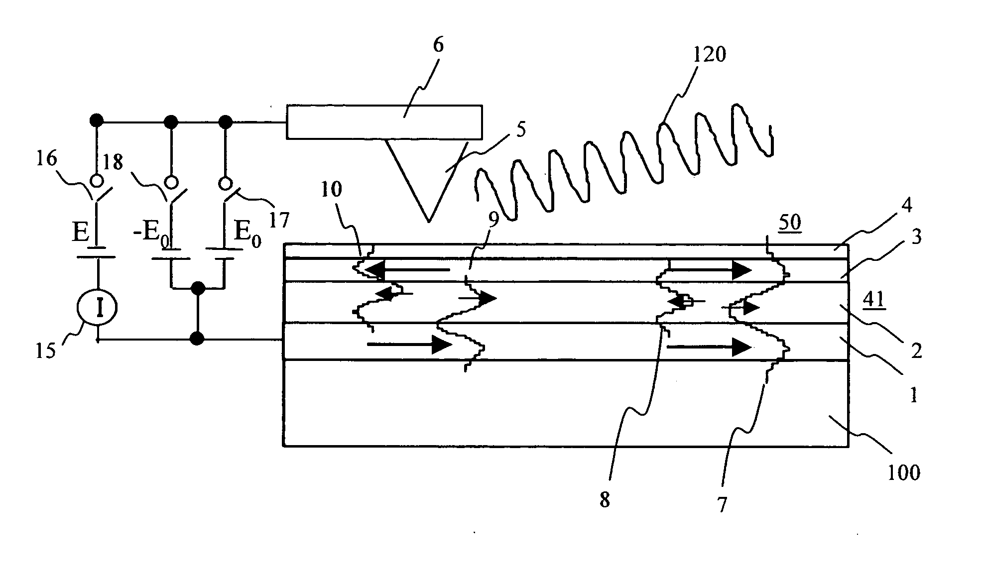
[0050]FIG. 1 shows a concept chart for describing a magnetization information recording / reproducing apparatus of the present invention. This apparatus is mainly configured by a magnetic recording medium 50, a metal probe 5 disposed so as to face the medium 50, and an irradiation light beam 120.

[0051] The magnetic recording medium 50 is configured by a multilayer film 41 formed by laminating a ferromagnetic metal layer 1, a nonmagnetic metal layer 2, a ferromagnetic metal layer 3, and a protection film 4 sequentially on a substrate 100. The metal probe 5 is disposed so as to face the surface of the protection film 4 with a 1 nm order gap therebetween. The metal probe 5 is held by a slider mechanism 6 structured just like that of a hard disk drive. At this time, a tunnel current may be used as a feedback signal for controlling the distance (gap) between the protection film 4 and the metal probe 5. The feedback signal may also be generated using an optical lever method used in an ordi...

second embodiment

[0067]FIG. 10 shows a concept chart of the magnetization information recording / reproducing apparatus in another embodiment of the present invention. Unlike the magnetic recording medium 50 shown in FIG. 1, the magnetic recording medium 50 in this second embodiment shown in FIG. 10 includes an anti-ferromagnetic layer 51 formed between the substrate 100 and the ferromagnetic metal layer 1 in addition to the multilayer film 41 consisting of a ferromagnetic metal layer 1, a nonmagnetic metal layer 2, a ferromagnetic metal layer 3, and a protection film 4 laminated sequentially on the substrate 100. This is a difference between those media 50.

[0068] Even in this second embodiment, the state of the quantum well electrons is the same as that in the first embodiment. And, as shown in the right half of FIG. 10, if the magnetizing directions of the ferromagnetic metal layers 1 and 3 are parallel to each other, the electrons having an electronic spin in the opposite magnetizing direction of ...

third embodiment

[0070]FIG. 11 shows a concept chart of the magnetization information recording / reproducing apparatus in still another (third) embodiment of the present invention. In this third embodiment, the protection film 4 and the ferromagnetic metal layer 3 included in the multilayer film are dot-patterned by a lithographic technique. The lithographic technique is employed widely for such manufacturing processes of semiconductor devices as resist patterning, ion milling, resist removing, etc. Each of those layers 4 and 3 has many nano-pillars 53 and 54 disposed at regular pitches. FIG. 12 shows a bird-view of such a recording medium having a plurality of nano-pillars 53 and 54.

[0071]FIG. 13 shows another structure of the recording medium having nano-pillars. FIG. 13A shows an example of nano-pillars formed by dot-patterning the structure of a multilayer film consisting of a protection film 4, a ferromagnetic layer 3, a nonmagnetic metal layer 2, a ferromagnetic layer 1, and an anti-ferromagne...


PUM

PropertyMeasurementUnit
energyaaaaaaaaaa
energyaaaaaaaaaa
bias voltageaaaaaaaaaa

Abstract

An information storage device having a hard disk has a metal probe that is brought closely to the surface of a multilayer film that includes a magnetic metal layer, a non-magnetic metal layer, and a magnetic metal layer up to a nano-meter order distance from the surface. The distance between the metal probe and the surface of the multilayer film, as well as the voltage to be applied are changed to change the state of the quantum well generated in the multilayer film, thereby changing the magnetizing direction relatively between the two magnetic metal layers. To read magnetization information from the hard disk, a change of an optically induced tunnel current is used. The change of the tunnel current is caused by a change of a plasmon resonance energy according to a relative change of the magnetizing direction between the magnetic metal layers.

Description

FIELD OF THE INVENTION [0001] The present invention relates to a method and apparatus for recording / reproducing magnetization information, more particularly to a new method and apparatus for recording / reproducing magnetization information, preferred for high density recording. BACKGROUND OF THE INVENTION [0002] Conventionally, a magnetic head has been used to write magnetization information in a hard disk drive (HDD). The magnetic head uses a magnetic field generated from a coil. And, the HDD recording density has been required to become higher and higher. As known well, when an HDD magnetic head becomes minute such way to meet the recording domain that becomes minute more and more as a result of achievement of such high density recording, the magnetic field to be generated from the magnetic head becomes weak under the influence of anti-magnetic field components generated from the tip of the magnetic head. In addition, if the recording domain becomes minute such way, the magnetizing...

Claims


Application Information

Patent Timeline
Patent Type & Authority Applications(United States)
IPC IPC(8): G11B5/66D06N7/04G11B5/02G11B5/738G11B9/14G11B11/00
CPCB82Y10/00G11B5/743G11B2005/0002G11B9/1472G11B9/1481G11B9/14
Inventor OGAWA, SUSUMUITO, KENCHI
Owner HITACHI LTD
Why Eureka
Try Eureka