Oil recovery using non-cryogenically produced nitrogen and off-gas recycling

Inactive Publication Date: 2005-06-23
GENERON IGS
View PDF6 Cites 1 Cited by
  • Summary
  • Abstract
  • Description
  • Claims
  • Application Information

AI Technical Summary

Benefits of technology

[0011] The invention has the further object of providing an enhanced oil recovery process in which the size and power requirements for a non-cryogenic gas generator are reduced.
[0012] The invention has the further object of providing an enhanced oil recovery process, in which off-gases withdrawn from an oil-bearing formation are used in the recovery process and are not discarded.
[0013

Problems solved by technology

But providing gaseous nitrogen in cylinders is cumbersome and expensive, especially where the well

Method used


Image

  • Oil recovery using non-cryogenically produced nitrogen and off-gas recycling
  • Oil recovery using non-cryogenically produced nitrogen and off-gas recycling

Examples


Embodiment Construction

[0018] In this specification, the terms “oil well”, “formation”, and “reservoir” are used interchangeably to identify a natural underground source of liquid oil.

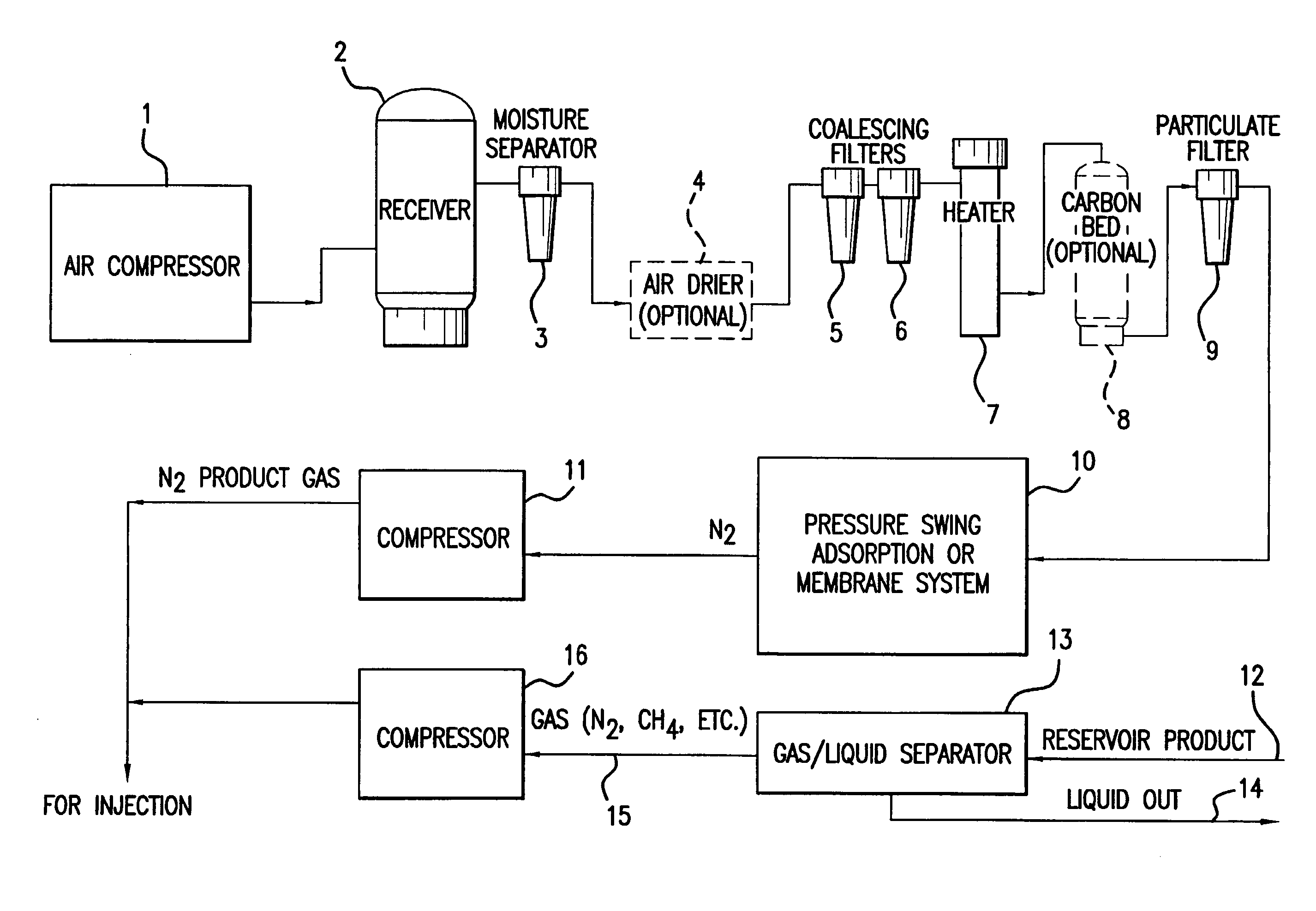
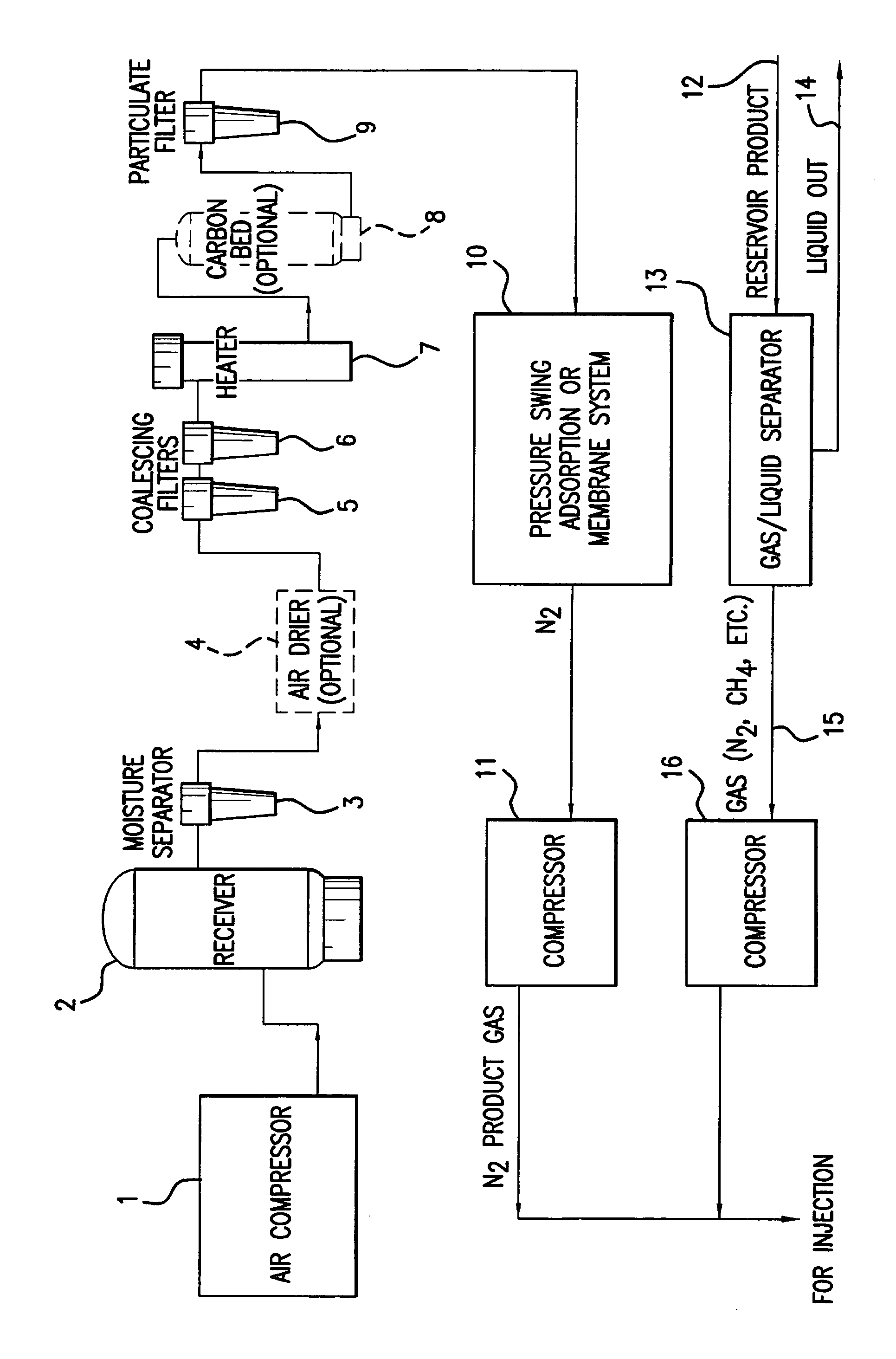
[0019] The FIGURE provides a schematic diagram of the components of a system used to practice the present invention. The system is preferably physically located at or near the site of an oil well.

[0020] Air compressor 1 takes ambient air and compresses it. The compressed air passes through receiver 2 and moisture separator 3. The air may then pass through an optional air dryer 4. The air passes through coalescing filters 5 and 6, and heater 7. Air leaving the heater may pass through an optional carbon bed 8, and then through particulate filter 9.

[0021] Air leaving the particulate filter enters air separator 10, which may be either a membrane system or a pressure swing adsorption (PSA) unit. The air separator converts the incoming air into two streams, one which is oxygen-enriched and the other which is oxygen-depleted (ni...


PUM


Abstract

An enhanced oil recovery process includes non-cryogenically generating a relatively inert gas, such as nitrogen, or nitrogen-enriched air, near the site of an oil-bearing formation. The relatively inert gas is injected into the formation, so as to displace oil from the formation. One or more off-gases, also obtained from the formation with the oil, are separated from the oil, compressed, and recycled into the formation. The use of the compressed off-gas therefore reduces the amount of relatively inert gas required, and reduces the required size and energy consumption of the equipment used to produce the inert gas. The invention therefore substantially reduces the cost of an enhanced oil recovery process.

Description

BACKGROUND OF THE INVENTION [0001] The present invention relates to the field of recovery of oil from oil wells, and provides an improved method for enhanced oil recovery. [0002] Enhanced oil recovery means the recovery of oil with the assistance of a compressed fluid which is pumped into a well so as to force the oil out. Such a technique is appropriate where the oil in the reservoir exists naturally in liquid form, but where the pressure of the oil is too low to cause the oil to exit the reservoir spontaneously. Such reservoirs typically include a mixture of liquid oil and natural gas, and may have some oxygen mixed therewith. [0003] In the prior art, it has been known to use a relatively inert gas, such as nitrogen or nitrogen-enriched air, to force the oil out of a reservoir. An inert gas, or relatively inert gas, is preferred, so as to prevent the fluid from reacting with the contents of the reservoir. A stream of compressed nitrogen, or other relatively inert gas, effectively ...

Claims


Application Information

Patent Timeline
IPC IPC(8): E21B43/16E21B43/40
CPCE21B43/40E21B43/166
Inventor NEWTON, DONALD E.JENSVOLD, JOHN A.
Owner GENERON IGS
Why Eureka
Try Eureka