Magnetoresistance effect element having a nonmagnetic intermediate layer having a two-dimensional fluctuation of resistance
a resistance element and nonmagnetic intermediate layer technology, applied in the field of magnetoresistance effect elements, can solve the problems of limiting the increase of the mr rate of change, difficult to acquire the value which exceeds 20%, and not desirable that the resistance of the element itself becomes large, etc., to achieve large resistance change, high sensitivity, and stable obtained
- Summary
- Abstract
- Description
- Claims
- Application Information
AI Technical Summary
Benefits of technology
Problems solved by technology
Method used
Image
Examples
first example
[0099] First, the first example of the invention will be explained.
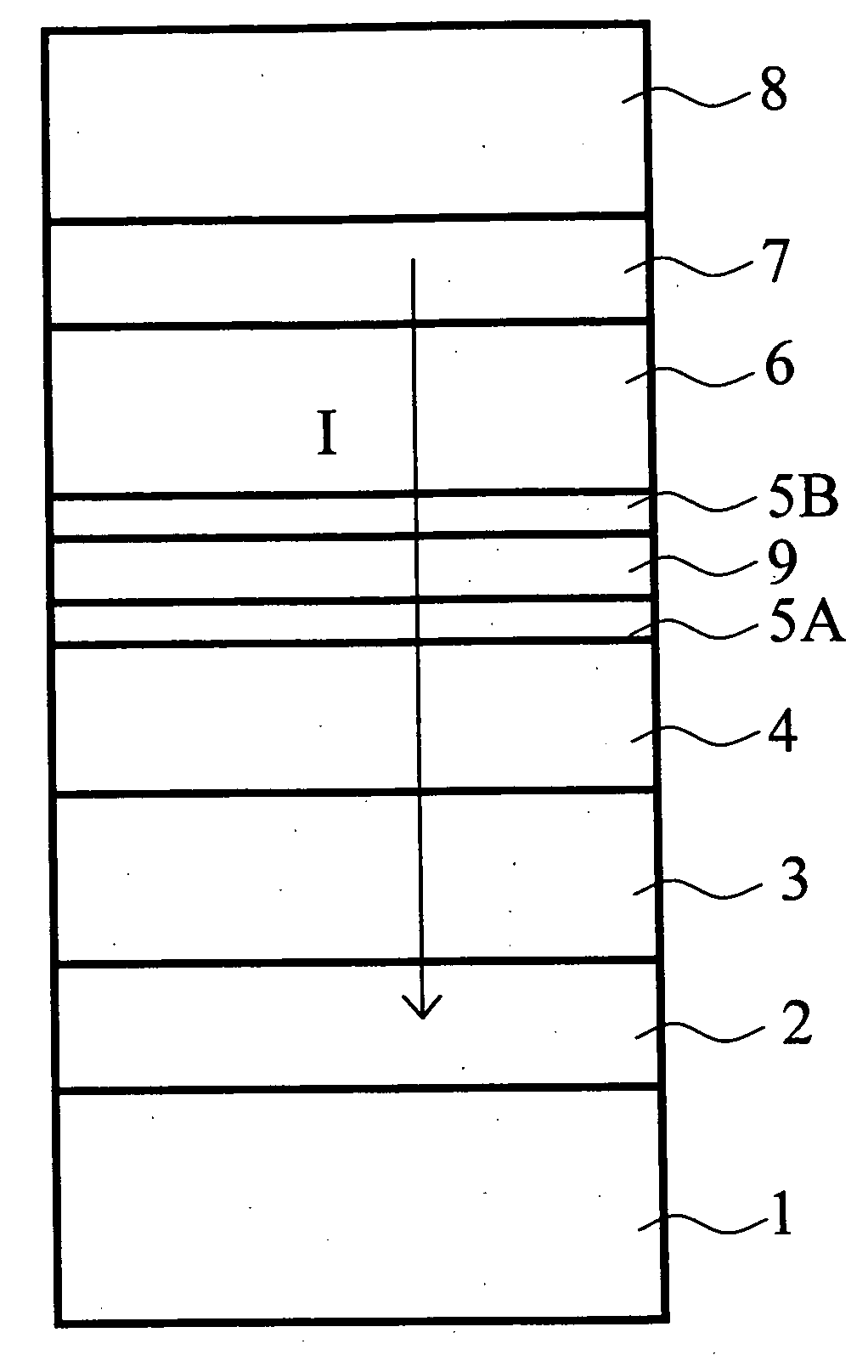
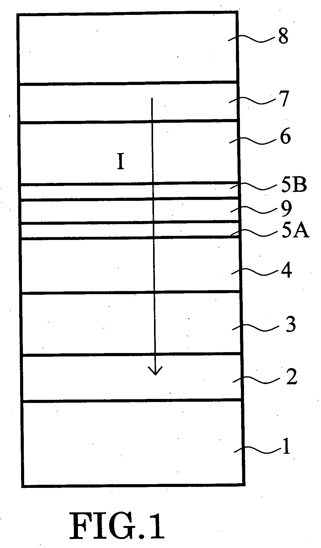
[0100] In this example, the magnetoresistance effect element of the structure expressed in FIG. 1 was manufactured with the comparative example.
[0101] That is, after forming the substrate electrode 1, the spin valve of the following film structure was formed on it: [0102] 5Ta / 2Ru / 15PtMn / 4CoFe / 1Ru / 4CoFe / intermediate-layer / 4CoFe / 1CU / 10Ta
[0103] In the above, each number expresses the Thickness (in nanometer) of the layer. This structure was formed by a DC magnetron sputtering. Then, annealing of 10 hours was performed at 270 degrees centigrade. And a patterning process was carried out to the planer shape into squares whose sizes ranged from 0.15 microns to 3 microns. Furthermore, after the surroundings of the patterned spin valve were filled up with insulators, such as alumina and a silicon oxide, the upper electrode 8 was formed, and thus the element having a structure of passing current perpendicularly to a film pl...
second example
[0125] Next, the example of the CPP type magnetoresistance effect element which can be used as a magnetic head is given and explained as the second example of the invention.
[0126]FIGS. 4 and 5 are conceptual diagrams which express typically the principal part structure of the magnetoresistance effect element concerning the embodiment of the invention. That is, these figures express the state where the magnetoresistance effect element is included in the magnetic head. FIG. 4 is a sectional view of the magnetoresistance effect element cut in parallel to the medium facing surface P which is opposite to a magnetic recording medium (not shown). FIG. 5 is a sectional view of the magnetic resistance effect element cut in the perpendicular direction to the medium opposite side P.
[0127] The magnetoresistance effect element illustrated in FIGS. 4 and 5 has a hard abutted structure. The lower electrode 12 and the upper electrode 20 are provided in the upper and lower sides of the magnetoresi...
third example
[0132] Next, a magnetic reproducing apparatus having inboard the magnetoresistance effect element of the embodiment will be explained as the third example of the invention.
[0133] That is, the magnetoresistance effect element or the magnetic head explained with reference to FIGS. 1 through 5 can be incorporated in a recording / reproducing magnetic head assembly and mounted in a magnetic reproducing apparatus.
[0134]FIG. 6 is a perspective view that shows outline configuration of this kind of magnetic reproducing apparatus. The magnetic reproducing apparatus 150 shown here is of a type using a rotary actuator. A magnetic reproducing medium disk 200 is mounted on a spindle 152 and rotated in the arrow A direction by a motor, not shown, which is responsive to a control signal from a controller of a driving mechanism, not shown. The magnetic reproducing apparatus 150 shown here may have a plurality of medium disks 200 inboard.
[0135] The medium disk 200 may be of a “lateral recording typ...
PUM
| Property | Measurement | Unit |
|---|---|---|
| thickness | aaaaa | aaaaa |
| resistance | aaaaa | aaaaa |
| total thickness | aaaaa | aaaaa |
Abstract
Description
Claims
Application Information
 - R&D
- Intellectual Property
- Life Sciences
- Materials
- Tech Scout
- Unparalleled Data Quality
- Higher Quality Content
- 60% Fewer Hallucinations
Browse by: Latest US Patents, China's latest patents, Technical Efficacy Thesaurus, Application Domain, Technology Topic, Popular Technical Reports.
© 2025 PatSnap. All rights reserved.Legal|Privacy policy|Modern Slavery Act Transparency Statement|Sitemap|About US| Contact US: help@patsnap.com


