Selective self-initiating electroless capping of copper with cobalt-containing alloys

a cobalt-containing alloy and self-initiating technology, applied in the direction of liquid/solution decomposition chemical coating, solid/suspension decomposition chemical coating, coating, etc., can solve the problems of reducing the reliability of the overall circuit of the formed device, and unable to meet the requirements of electroless deposition

Inactive Publication Date: 2005-06-23
APPLIED MATERIALS INC
View PDF99 Cites 47 Cited by
  • Summary
  • Abstract
  • Description
  • Claims
  • Application Information

AI Technical Summary

Benefits of technology

[0024] In another embodiment, an apparatus for forming an electroless deposition solution is provided which includes a first vessel containing a conditioning buffer solution comprising a citrate, a second vessel containing a metal-containing solution comprising a metal source and citrate, a third vessel containing a buffered reducing solution comprising a hypophosphite source

Problems solved by technology

The formation of copper oxides at the interface between metal layers can increase the resistance (e.g., copper interconnects) and reduce the reliability of the overall circuit in the formed device.
Electroless deposition on copper using standard electroless solutions has been problematic since these materials are generally not able to satisfactorily catalyze or initiate deposition.
While deposition of cobalt-containing alloys may be easily initiated electrochemically (e.g., by applying a sufficiently negative potential), a continuous conductive

Method used


Image

  • Selective self-initiating electroless capping of copper with cobalt-containing alloys
  • Selective self-initiating electroless capping of copper with cobalt-containing alloys
  • Selective self-initiating electroless capping of copper with cobalt-containing alloys

Examples


examples

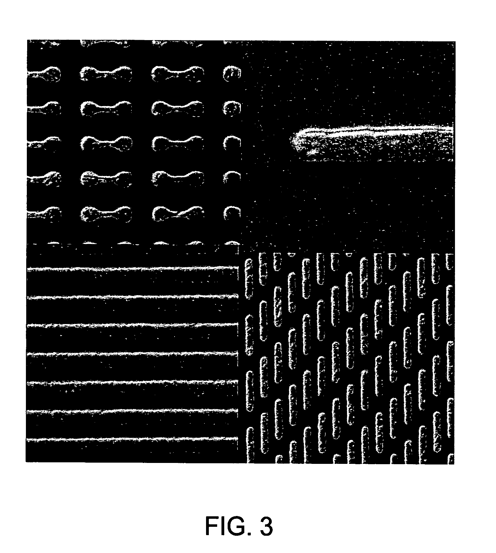
[0102] In the following examples, 300 mm silicon AMAT MTC CD90 E-test pattern wafers were used as sample substrates for electroless deposition of cobalt-containing alloys. The substrates contained exposed copper interconnect structures, such as lines, pads and vias, that were electrically isolated within the dielectric film. The substrate surface was polished by a CMP process and subsequently selectively coated with a CoWP alloy film by an electroless plating process, as described in embodiments above. The plating process utilized a face up “puddle plating” process. Continuous and uniform cobalt-containing films were selectively grown on the different copper surfaces as shown by images from a scanning electron microscope (SEM), as shown in FIG. 3.

[0103] In FIG. 4, the measured electrical performance of interconnect lines with cobalt capping layers shows no significant difference of current leakage compared with the same line structures without cobalt-containing capping layers, as s...


PUM

PropertyMeasurementUnit
Temperatureaaaaaaaaaa

Abstract

Embodiments of the invention generally provide compositions of plating solutions, methods to mix plating solutions and methods to deposit capping layers with plating solutions. The plating solutions described herein may be used as electroless deposition solutions to deposit capping layers on conductive features. The plating solutions are rather dilute and contain strong reductants to self-initiate on the conductive features. The plating solutions may provide in-situ cleaning processes for the conductive layer while depositing capping layers free of particles. In one embodiment, a method for forming an electroless deposition solution is provided which includes forming a conditioning buffer solution with a first pH value and comprising a first complexing agent, forming a cobalt-containing solution with a second pH value and comprising a cobalt source, a tungsten source and a second complexing agent, forming a buffered reducing solution with a third pH value and comprising a hypophosphite source and a borane reductant, combining the conditioning buffer solution, the cobalt-containing solution and the buffered reducing solution to form the electroless deposition solution. The electroless deposition solution includes the cobalt source in a concentration range from about 1 mM to about 30 mM, the tungsten source in a concentration range from about 0.1 mM to about 5 mM, the hypophosphite source in a concentration range from about 5 mM to about 50 mM, the borane reductant in a concentration range from about 5 mM to about 50 mM, and has a total pH value in a range from about 8 to about 10.

Description

CROSS-REFERENCE TO RELATED APPLICATIONS [0001] This application claims benefit of U.S. Provisional Patent Application Ser. No. unknown, entitled, “Self-Activating Electroless Deposition Process for Cobalt-Containing Alloys,” filed Oct. 7, 2004, and U.S. Provisional Patent Application Ser. No. 60 / 512,334, entitled, “Self-Activating Electroless Deposition Process for CoWP Alloys,” filed Oct. 17, 2003, which are both herein incorporated by reference.BACKGROUND OF THE INVENTION [0002] 1. Field of the Invention [0003] Embodiments of the invention generally relate to compositions, kits and methods for forming and using electroless deposition solutions to deposit capping layers over conductive layers in electronic devices, and more particularly for depositing cobalt-containing layers on copper surfaces. [0004] 2. Description of the Related Art [0005] Copper and its alloys have become the metals of choice for sub-micron interconnect technology because copper has a lower resistivity than alu...

Claims


Application Information

Patent Timeline
IPC IPC(8): B05D1/18C23C18/16C23C18/18C23C18/31C23C18/34C23C18/36C23C18/40C23C18/44C23C18/48C23C18/50C23C18/52H01L21/288H01L21/768
CPCC23C18/1619C23C18/168C23C18/1841H01L21/76874H01L21/288H01L21/76849C23C18/50
Inventor WEIDMAN, TIMOTHYZHU, ZHIZE
Owner APPLIED MATERIALS INC
Why Eureka
Try Eureka