
Vehicle energy management system using prognostics

a technology of vehicle energy management and prognostic, applied in adaptive control, instruments, tractors, etc., can solve the problems of increasing increasing the complexity of electrical systems in modem vehicles, and increasing the complexity of energy management strategies. achieve the effect of avoiding degraded electrical system performan

Inactive Publication Date: 2005-06-23
LEAR CORP
View PDF14 Cites 61 Cited by
  • Summary
  • Abstract
  • Description
  • Claims
  • Application Information

AI Technical Summary

Benefits of technology

[0007] The present invention has the advantage of providing an energy management control system for managing events in an electrical system based on forecasted states to avoid degraded electrical system performance without excessive processing requirements.

Problems solved by technology

Systems for generating, storing, conditioning, and using electric power in motor vehicles are becoming increasingly complex.
Due to the large number of interacting electrical components competing for capacity and each having various kinds of influences on electrical system performance, energy management strategies have become more extensive and complex.
However, the complex electrical systems in modem vehicles are characterized by high nonlinearity (e.g., stability of power flow, battery and alternator performance and interaction, and load current profiles) which are difficult to model.
However, advance prediction of the electrical system state is even more resource intensive and complicated.

Method used


Image

  • Vehicle energy management system using prognostics
  • Vehicle energy management system using prognostics
  • Vehicle energy management system using prognostics

Examples


Embodiment Construction

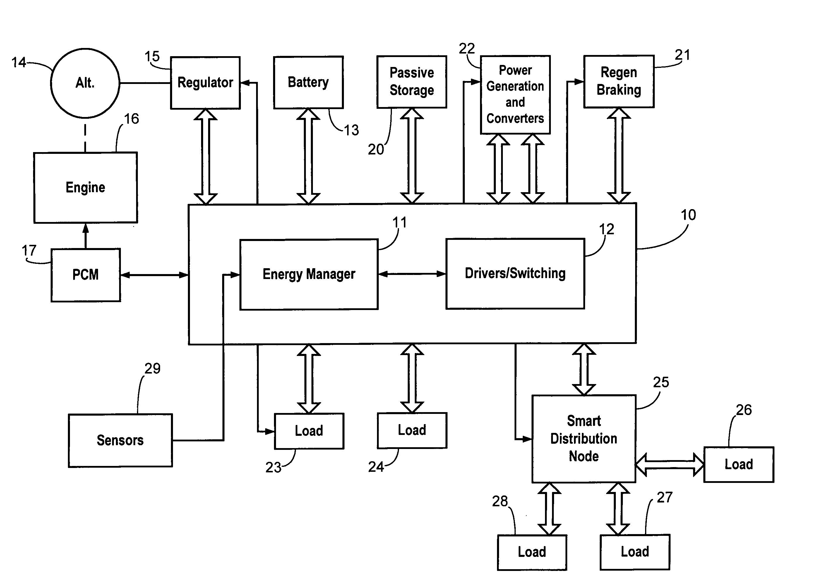
[0017] A typical electrical energy, power, and load management (EM) system controls power generation, storage, and consumption according to different operational states of a vehicle. The EM strategy optimizes the generation, distribution, and conversion of power in the vehicle electrical system as a function of electrical capacity / usage balancing, health status of electrical system components, and priority definitions for basic electrical system functions. Electrical system parameters that are monitored and controlled include load currents, battery state of charge (SOC), state of health (SOH), power generation capabilities of multiple sources (e.g., alternator and fuel cell), energy storage capabilities (e.g., ultracapacitors, regenerative braking), and power conversion capabilities (e.g., dc / dc and dc / ac converters). The controlled systems can include dual voltage architectures (e.g., 42 / 14 volt systems) and dual battery systems.

[0018] An EM system typically has the capability of ...


PUM


Abstract

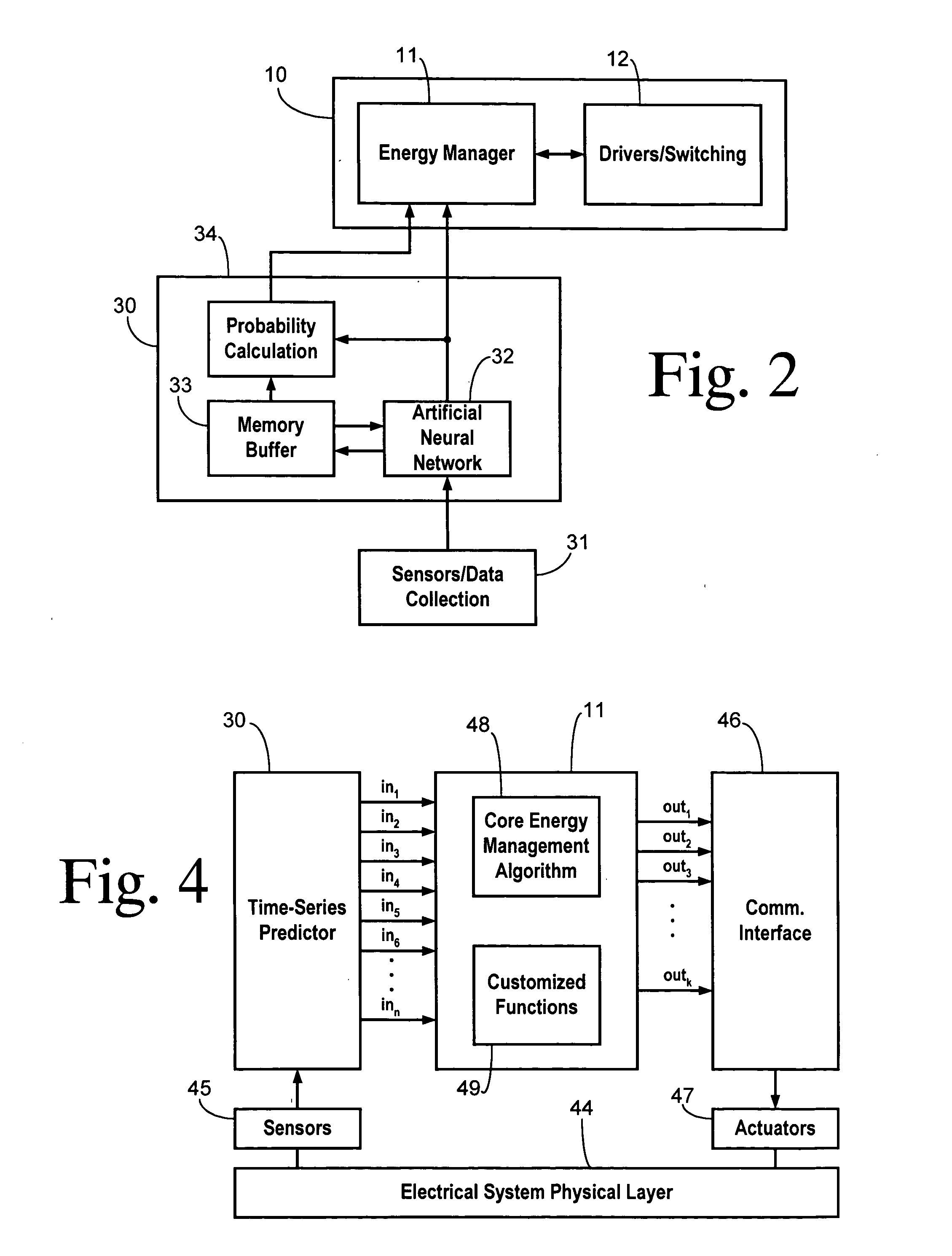
An energy management system for controlling an electrical system comprises data collection components, such as sensors, for providing quantified variables for forming an instantaneous state vector. A time series predictor generates an estimated future vector value in response to the instantaneous state vector. An electrical system manager includes predetermined decision rules invoked in response to the estimated future vector value to adapt the electrical system to expected electrical conditions.

Description

CROSS REFERENCE TO RELATED APPLICATIONS [0001] Not Applicable. STATEMENT REGARDING FEDERALLY SPONSORED RESEARCH [0002] Not Applicable. BACKGROUND OF THE INVENTION [0003] The present invention relates in general to controlling electrical systems in vehicles, and, more specifically, to use of a time-series predictor to improve energy management of an electrical system. [0004] Systems for generating, storing, conditioning, and using electric power in motor vehicles are becoming increasingly complex. New electrical functions, the increased use of power assist systems such as electric power-assist steering, new types of power generation systems such as integrated starter-alternator systems, fuel cells, dual battery systems, and 42-volt systems, require increasingly sophisticated control systems. Furthermore, the limited power capacity on a vehicle makes it desirable to be able to prioritize power delivery to various loads when electrical demand approaches or exceeds available supply. [00...

Claims


Application Information

Patent Timeline
Patent Type & Authority Applications(United States)
IPC IPC(8): B60K28/10B60R16/02B60R16/03B60W10/08B60W20/00B60W50/00G05B13/02G05B13/04G06F7/00
CPCB60R16/03B60W10/08B60W20/102Y02T10/84G05B13/026G05B13/027B60W2050/0057B60W20/11
Inventor ALVAREZ-TRONCOSO, IGNACIOPINAS, JOAN FONTANILLESGUASCH, JORDI MESTRE
Owner LEAR CORP
Learn More