
Particle therapy system

a particle therapy and system technology, applied in the field of particle therapy system, can solve the problems of prolonged standby time, reduced treatment efficiency, and relatively long time, and achieve the effects of shortening the beam setting time, increasing the number of patients treated, and greatly reducing the number of command value groups to be stored

Inactive Publication Date: 2005-06-30
HITACHI LTD
View PDF7 Cites 63 Cited by
  • Summary
  • Abstract
  • Description
  • Claims
  • Application Information

AI Technical Summary

Benefits of technology

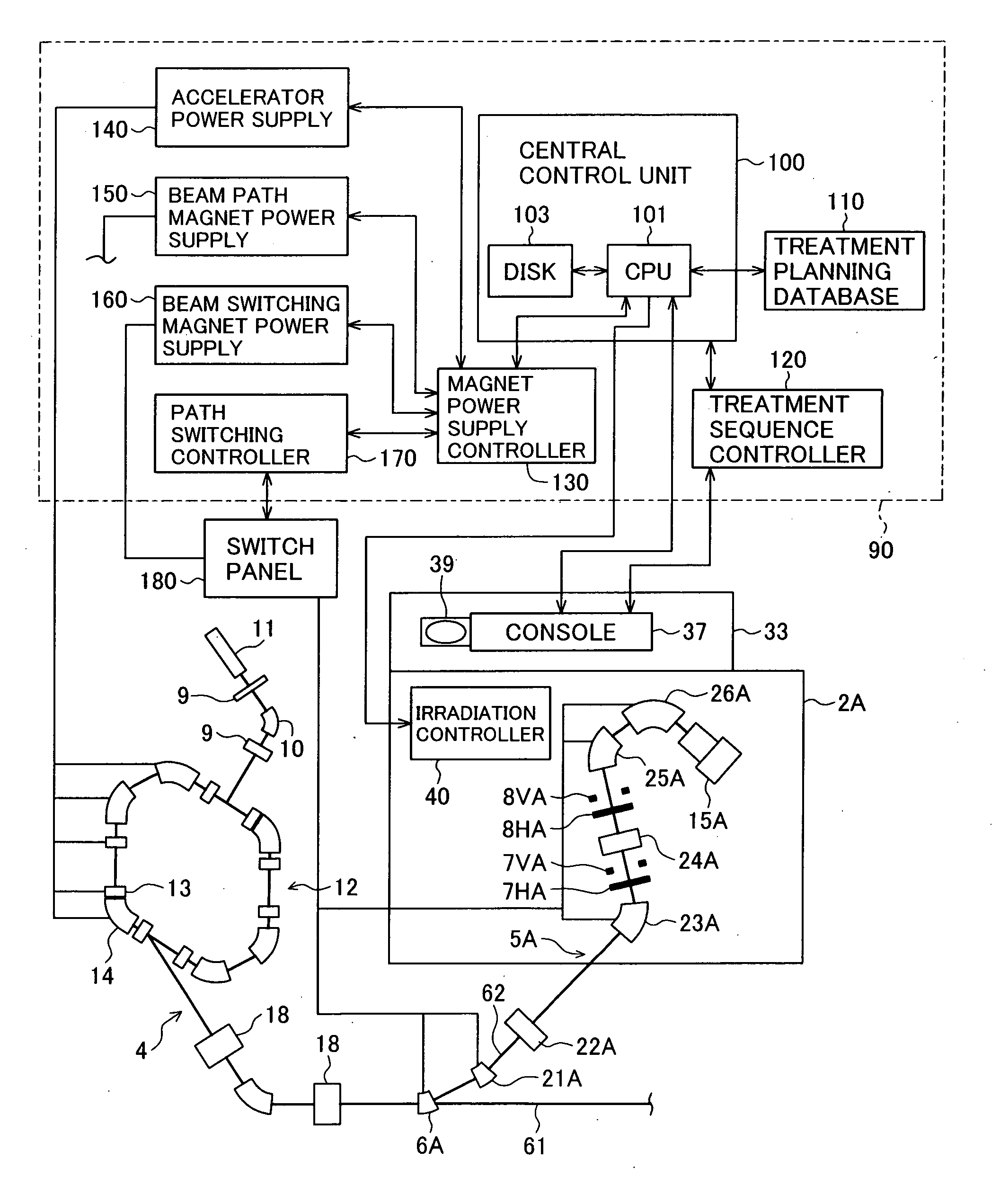
The present invention provides a particle therapy system with a plurality of treatment rooms that can increase the number of patients treated in one treatment room per unit time. This is achieved by producing a group of command values that command excitation currents for magnets disposed in a charged particle beam generator and a beam transport system, and by using the second command value group to command the excitation currents for other magnets when only the rotating gantry angle is different. The use of the second command value group can greatly reduce the search time required for specifying the necessary command value group and can shorten the beam setting time. Additionally, the invention includes an angle development computing unit for computing the second command value group depending on the rotation angle of the rotating gantry and an energy development computing unit for computing the first and second command value groups depending on the beam energy. This allows for a larger beam automatically settable range of the control unit and can enlarge the beam treatment room.

Problems solved by technology

This means that if the beam setting takes a long time, a standby time is prolonged and treatment efficiency lowers.
In the beam setting step, the control unit takes a relatively long time to search for, from among the very large number of command value groups, a particular command value group corresponding to the beam requested from the treatment room, and hence a time required for the beam setting is prolonged.

Method used


Image

  • Particle therapy system
  • Particle therapy system
  • Particle therapy system

Examples


Embodiment Construction

[0025] A particle therapy system, as one preferable embodiment of the present invention, will be described below with reference to the drawings.

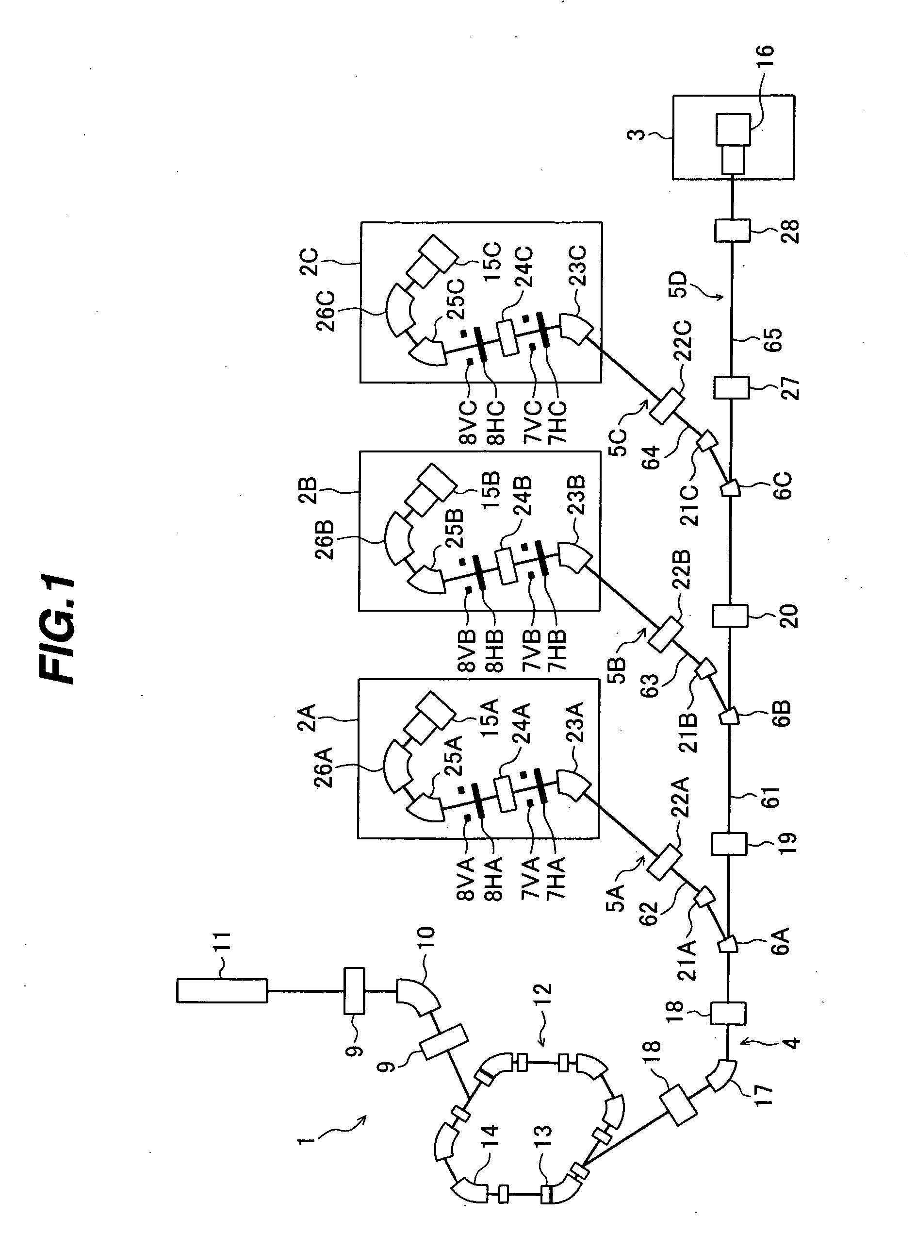
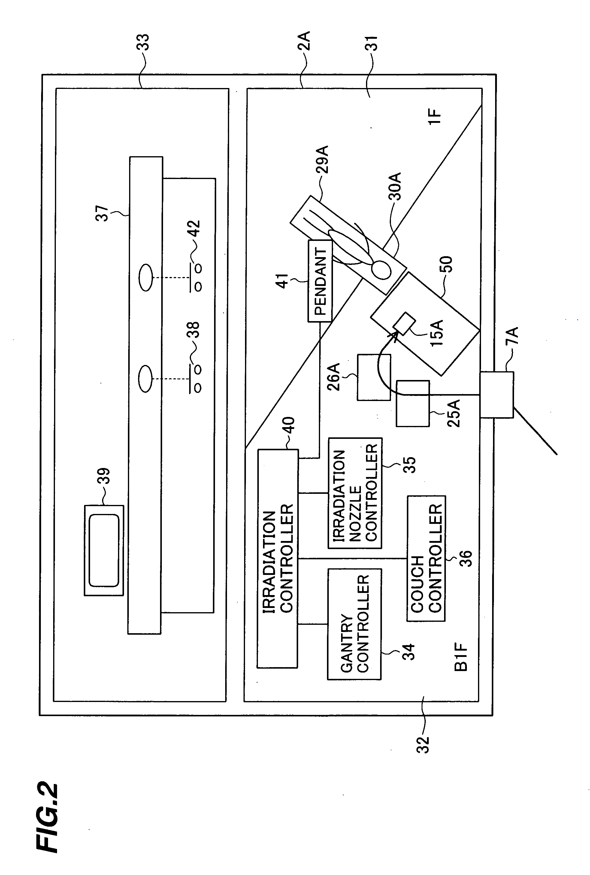
[0026] As shown in FIG. 1, a particle therapy system of this embodiment comprises a charged particle beam generator 1, four treatment rooms 2A, 2B, 2C and 3, a beam transport system made up of a first beam transport system (beam transport system in claims) 4 connected to the downstream side of the charged particle beam generator 1 and second beam transport systems (beam transport system in claims) 5A, 5B, 5C and 5D branched from the first beam transport system 4, and switching magnets 6A, 6B and 6C. The first beam transport system 4 serves as a common beam transport system for introducing an ion beam to each of the second beam transport systems 5A, 5B, 5C and 5D.

[0027] The charged particle beam generator 1 comprises an ion source (not shown), a pre-stage charged particle beam generator (linac) 11, and a synchrotron 12. Ions (e.g., proton o...


PUM


Abstract

A particle therapy system capable of increasing the number of patients treated in one treatment room per unit time. The particle therapy system comprises a charged particle beam generator for generating an ion beam, an irradiation apparatus for irradiating the ion beam extracted from the charged particle beam generator to an irradiation target, a beam transport system for transporting the ion beam extracted from the charged particle beam generator to the irradiation apparatus, and a central control unit for producing a set of command data to command excitation currents for magnets disposed in the charged particle beam generator and the beam transport system, the set of command data being classified into group-1 data and group-2 data.

Description

BACKGROUND OF THE INVENTION [0001] 1. Field of the Invention [0002] The present invention relates to a particle therapy system, and more particularly to a particle therapy system for irradiating a charged particle beam, such as a proton or carbon ion beam, to a diseased part for treatment. [0003] 2. Description of the Related Art [0004] There is known a therapy method of irradiating a charged particle beam, such as a proton beam, to a diseased part, e.g., a cancer, in the body of a patient. A large-scaled one of therapy systems used for practicing such a therapy method conventionally comprises a charged particle beam generator, a beam transport system, and a plurality of treatment rooms. The charged particle beam accelerated by the charged particle beam generator reaches an irradiation apparatus in each treatment room through the beam transport system, and it is irradiated to the diseased part in the patient body from a nozzle of the irradiation apparatus. For that purpose, the beam...

Claims


Application Information

Patent Timeline
Patent Type & Authority Applications(United States)
IPC IPC(8): A61N5/01A61N5/10G21K5/04G21K5/10H05H7/10H05H13/04
CPCA61N5/10G21K5/04A61N2005/1087A61N5/1079
Inventor CHIBA, DAISHUNFUJISHIMA, YASUTAKE
Owner HITACHI LTD
Learn More