Controller for permanent magnet alternator

a permanent magnet high-power, controller technology, applied in the field of machines, can solve the problems of reducing the efficiency of the alternator, so as to reduce radio frequency interference, reduce the switching energy, and increase the conversion efficiency

Inactive Publication Date: 2005-07-07
MAGNETIC APPL
View PDF12 Cites 59 Cited by
  • Summary
  • Abstract
  • Description
  • Claims
  • Application Information

AI Technical Summary

Benefits of technology

[0024] Increasing conversion efficiency and reducing radio frequency interference by limiting the rate of change of the voltage across and current through power switches employed in the system to minimize the switching energy that would otherwise be dissipated in the power switches as heat and, preferably, recapturing that switching energy directing it to the load.

Problems solved by technology

Accordingly, space constraints in vehicles tend to make such alternators difficult to use in high output, e.g., 5 KW, applications, such as for powering air conditioning, refrigeration, or communications apparatus.
In addition, the claw-pole type rotors, carrying windings, are relatively heavy (often comprising as much as three quarters of the total weight of the alternator) and create substantial inertia.
Such inertia, in effect, presents a load on the engine each time the engine is accelerated.
This tends to decrease the efficiency of the engine, causing additional fuel consumption.
In addition, such inertia can be problematical in applications such as electrical or hybrid vehicles.
The use of such electrical control and drive systems tends to increase the demand on the electrical power system of the vehicle.
Typically only a limited amount of space is provided within the engine compartment of the vehicle to accommodate the alternator.
Unless a replacement alternator fits within that available space, installation is, if possible, significantly complicated, typically requiring removal of major components such as radiators, bumpers, etc. and installation of extra brackets, belts and hardware.
Such voltage levels are difficult and, indeed, dangerous to handle.
In addition, such extreme variations in the voltage and current may require more expensive components; components rated for the high voltages and currents produced at high engine RPM (e.g., highway speeds) are considerably more expensive, than components rated for more moderate voltages.
However, particularly in compact high power, high speed ratio applications such as motor vehicles, the switching transitions between windings have deleterious effects, especially at the high end of the RPM range.
These solutions tend to involve mechanical components that are large, require maintenance and are subject to wear.
Flux diversion, however, typically requires additional mechanical components and can be slow to react.
In addition, the use of such a SCR bridge to derive a regulated output signal at voltages typically employed in automotive systems from the output of the alternator is likely to involve relatively higher peak currents, and higher switching (IR) losses manifested by the generation of significant amounts of heat and electromagnetic interferences.

Method used


Image

  • Controller for permanent magnet alternator
  • Controller for permanent magnet alternator
  • Controller for permanent magnet alternator

Examples


Embodiment Construction

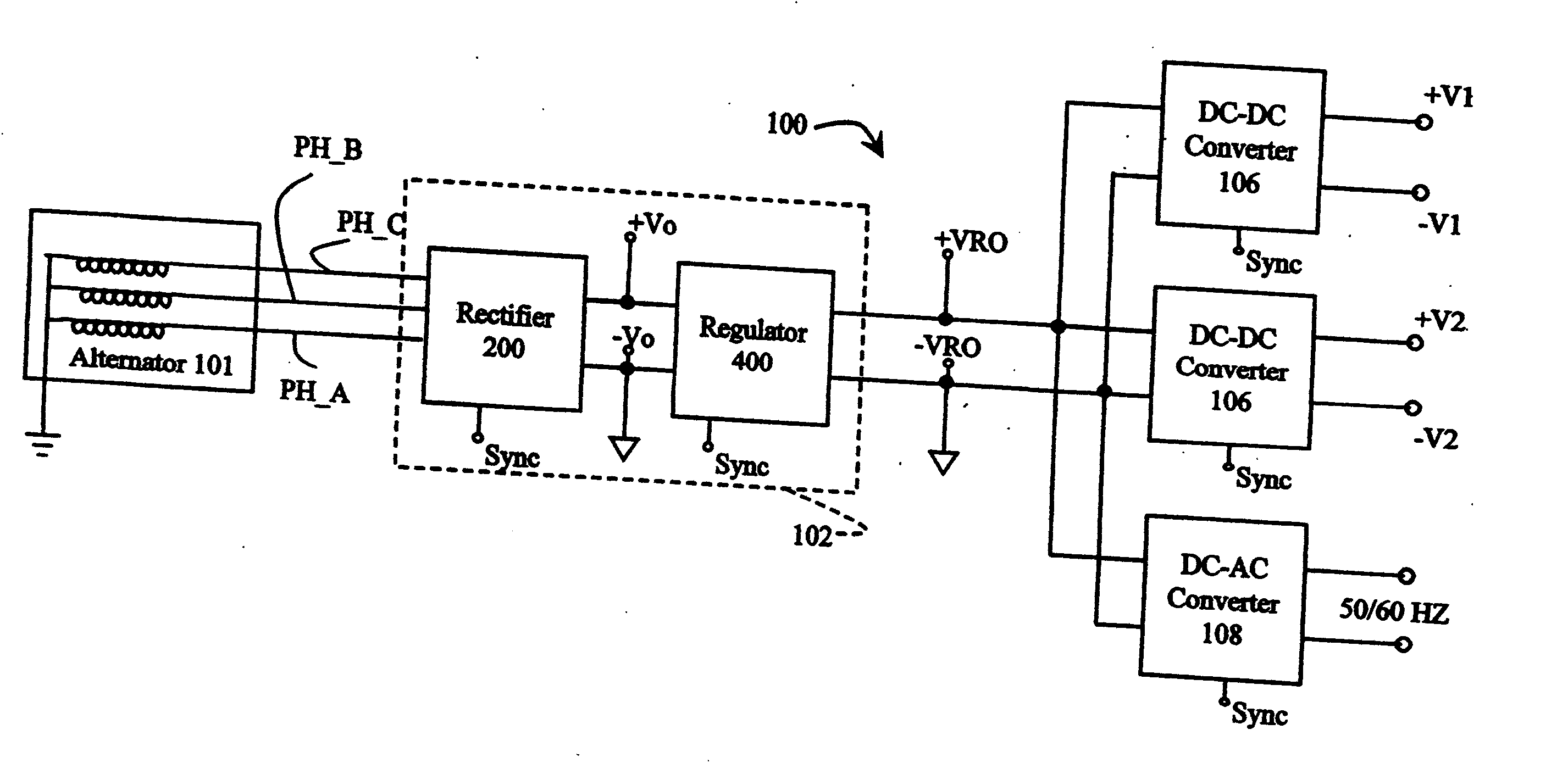
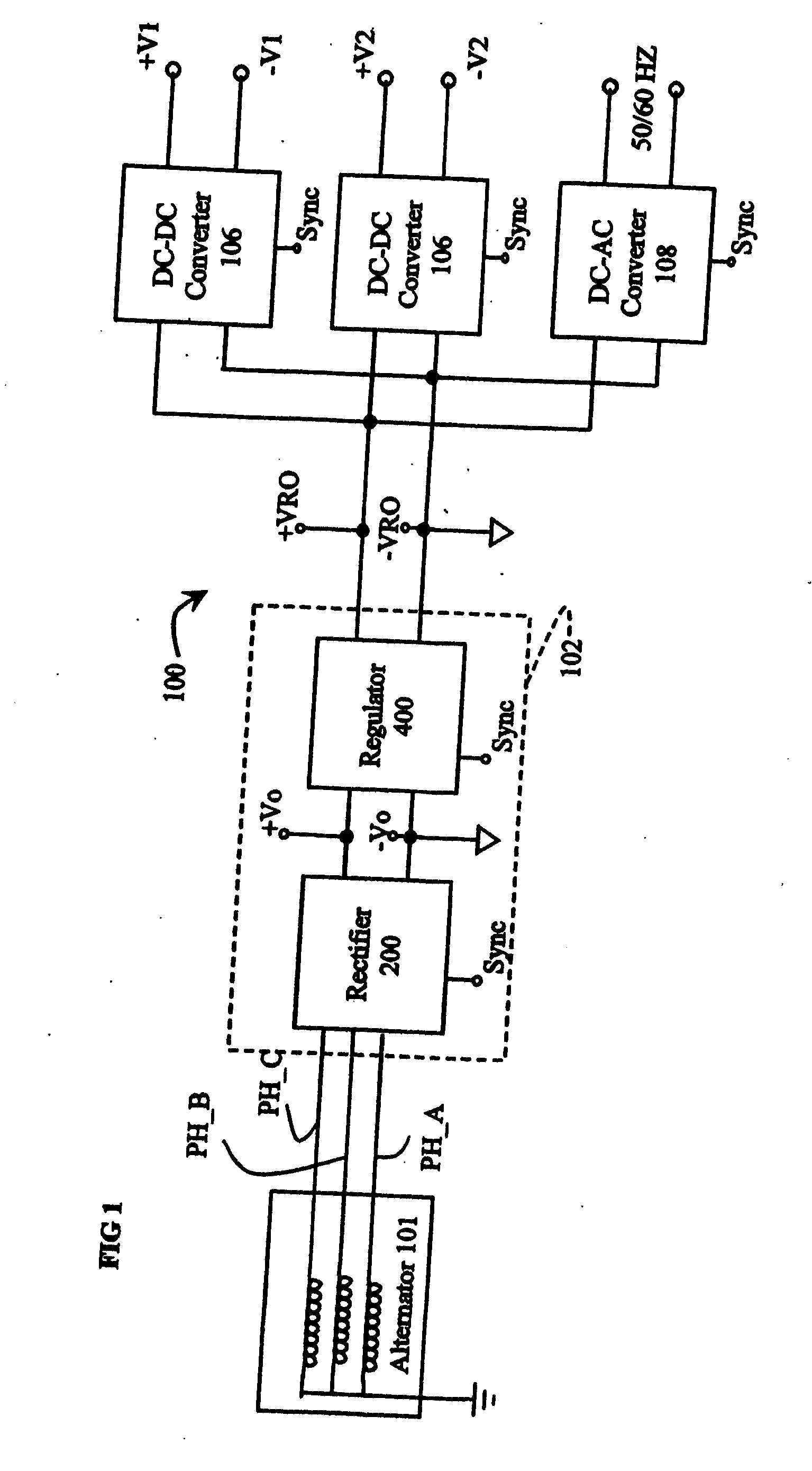
[0042] Referring now to FIG. 1, a system 100 for converting between mechanical and electrical energy in accordance with various aspects of the present invention comprises: an alternator 101, a rectification and regulation system 102 (suitably comprising a rectifier 200 and regulator 400), one or more DC-DC converters 106, and, suitably, a DC-AC inverter 108.

[0043] In general, alternator 101 provides multi-phase (e.g. three-phase) unregulated AC output signals, phase A (PH_A), phase B (PH_B), and phase C (PH_C) that vary significantly in accordance with drive RPM. Rectification and regulation system 102 rectifies the AC output signal from alternator 101, i.e. converts it into a DC signal (VRO), and regulates the voltage of that signal at a predetermined level, e.g. 180V, i.e., maintains the voltage level with a tolerance of ±2%. The regulated DC signal (VRO) is then applied to DC-DC converters 106 for conversion to a desired output voltage level(s) (V1, V2), e.g., 12, 24 and / or 42 v...


PUM


Abstract

The invention is a control system that, among other things, controls a permanent magnet alternator and provides relatively accurate voltage regulation. The control system may include one or more of the following: (1) a rectification system to rectify and regulate the output voltage of an alternator, (2) a rectifier/limiter used as an electrical power source to a boost type regulator, (3) a multimode rectifier/limiter, (4) a DC to AC inverter bridge, and (5) power switches employed in the system to minimize the switching energy that would otherwise be dissipated in the power switches as heat.

Description

RELATED APPLICATIONS [0001] This application claims priority to U.S. Provisional Application Ser. No. 60 / 475,273, filed Jun. 2, 2003, the disclosure of which is incorporated herein by reference, and U.S. Provisional Application Ser. No. 60 / 532,664, filed Dec. 24, 2003.TECHNICAL FIELD OF THE INVENTION [0002] The present invention relates to machines for converting between mechanical and electrical energy, and in particular to a compact permanent magnet high power alternator suitable for automotive use, and to voltage and current control systems for such generators. BACKGROUND OF THE INVENTION [0003] An alternator typically comprises a rotor mounted on a rotating shaft and disposed concentrically relative to a stationary stator. The rotor is typically disposed within the stator. However, the stator may be alternatively positioned concentrically within the rotor. An external energy source, such as a motor or turbine, commonly drives the rotating element, directly or through an intermed...

Claims


Application Information

Patent Timeline
Patent Type & Authority Applications(United States)
IPC IPC(8): B60L50/10H02H7/06H02M7/217H02P9/00H02P9/30H02P9/48H02P11/00
CPCB60L11/02H02M7/2176H02P9/307Y02T10/70Y02T10/642Y02T10/7077H02P9/48B60L50/10H02M1/0085Y02T10/64Y02T10/7072H02P9/14H02P9/30
Inventor QUAZI, FAZLESCOTT, HAROLD C.KOCH, STEWART C.
Owner MAGNETIC APPL
Why Eureka
Try Eureka