Exposure apparatus and device manufacturing method

a technology of exposure apparatus and manufacturing method, which is applied in the direction of photomechanical apparatus, instruments, printing, etc., can solve the problems of large and complex apparatus, deterioration of exposure apparatus, and fluid lowering resolution, so as to facilitate the reduction of local thermal strain on the wafer

Inactive Publication Date: 2005-07-07
CANON KK
View PDF13 Cites 571 Cited by
  • Summary
  • Abstract
  • Description
  • Claims
  • Application Information

AI Technical Summary

Benefits of technology

[0005] Accordingly, it is an exemplary object of the present invention to provide an exposure apparatus for easily reducing the local thermal strain on the wafer generated by the temperature difference between the wafer and the fluid to be supplied to a space between the projection optical system and the wafer for the immersion exposure.

Problems solved by technology

However, if a temperature difference occurs between the fluid and the wafer, a local thermal strain generates on the wafer, a change of the refractive index of the fluid lowers the resolution, and the yield of the exposure apparatus deteriorates consequently.
However, this method makes the structure of the exposure apparatus large and complex, and causes the fluid surface to swell as the stage moves, deteriorating the positioning performance of the stage, and dispersing the fluid.

Method used


Image

  • Exposure apparatus and device manufacturing method
  • Exposure apparatus and device manufacturing method
  • Exposure apparatus and device manufacturing method

Examples


first embodiment

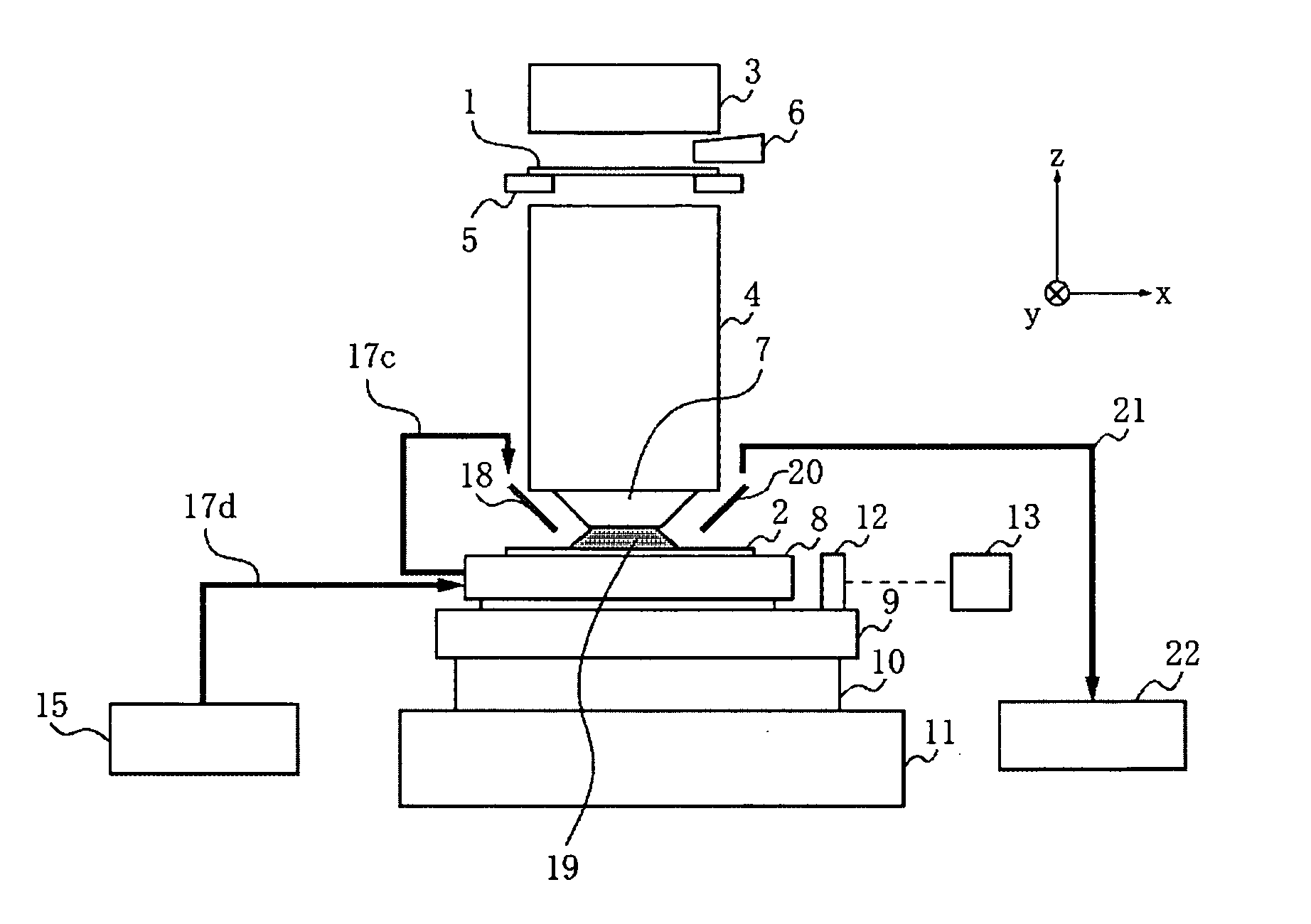
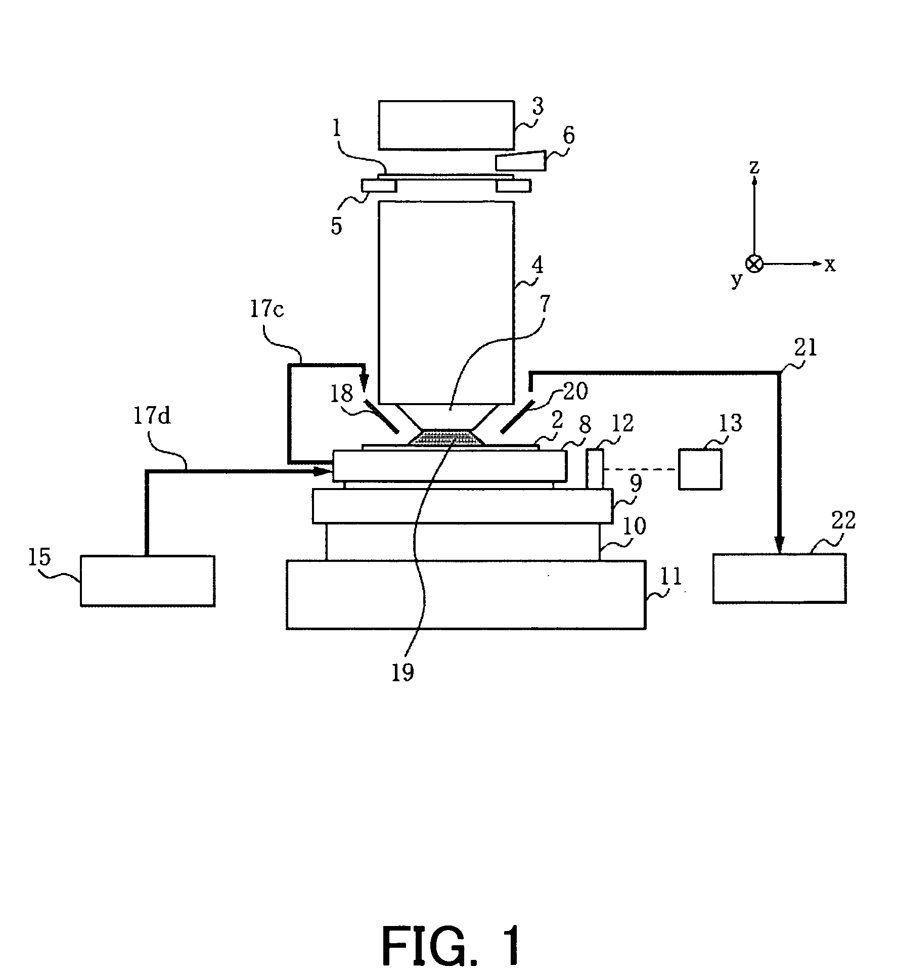
[0020]FIG. 1 shows a structure of an exposure apparatus according to a first embodiment of the present invention. The exposure apparatus of this embodiment uses a method (or so-called local fill system) that introduces the fluid only in the space between the wafer and the projection optical system. In FIG. 1, 1 denotes a mask (or a reticle) as an original that has a circuit pattern. 2 denotes a photosensitive agent applied wafer as a substrate onto which the circuit pattern on the mask 1 is exposed and transferred. 3 denotes an illumination optical system that includes a shutter, a dimmer, etc. and illuminates the mask using the light from the light source (not shown). 4 denotes a projection optical system for projecting a pattern on the mask 1 onto the wafer 2. 5 denotes a mask stage that holds the mask 1, and positions the mask 1 at a predetermined position. 6 denotes an alignment optical system used to position the mask 1 and align the mask image with the circuit pattern that has...

second embodiment

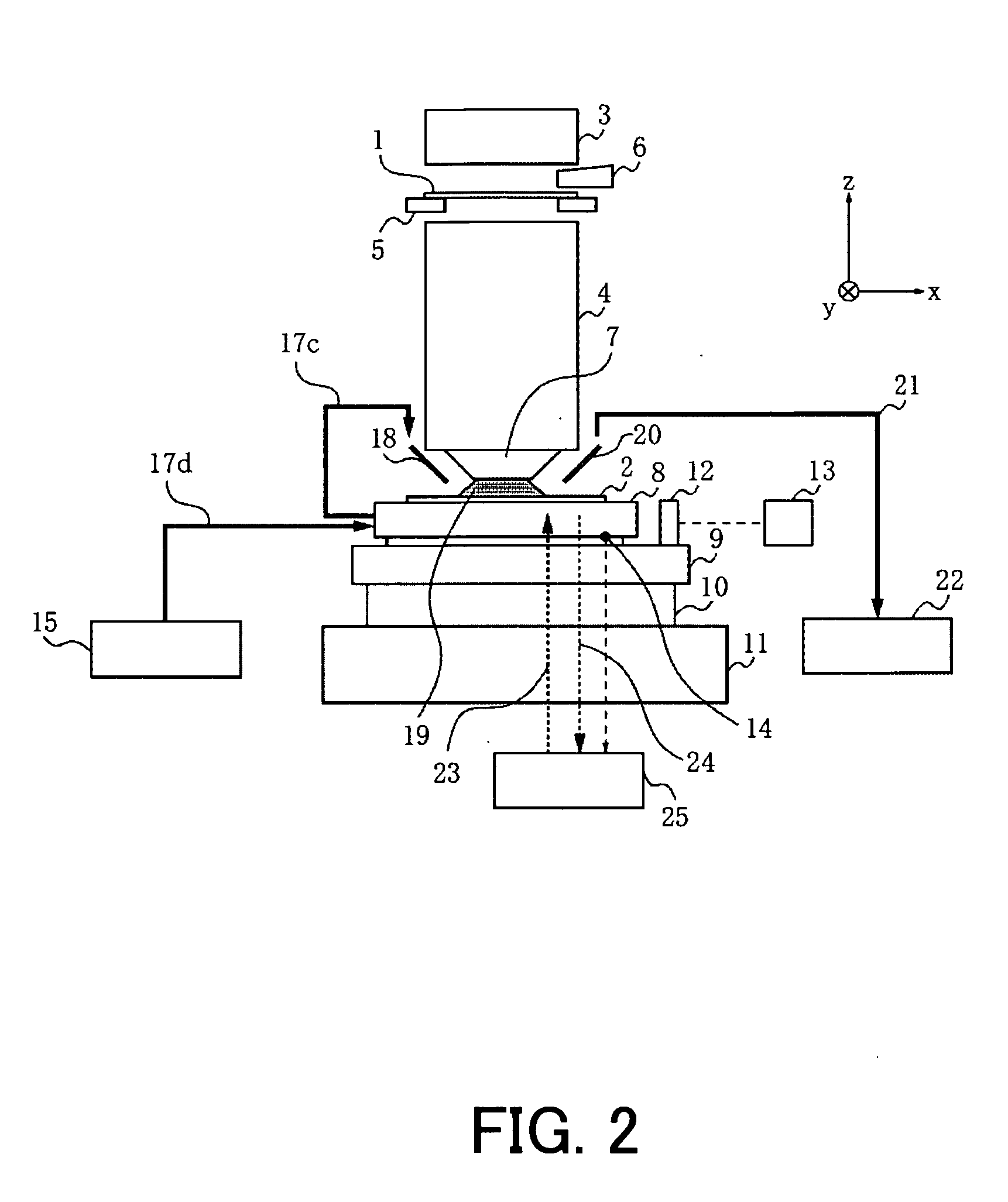
[0025]FIG. 2 shows a structure of an exposure apparatus according to a second embodiment of the present embodiment. Each element in FIG. 2 which is the same as corresponding element in FIG. 1 is designated by the same reference numeral as that shown in the first embodiment. The following description focuses on a difference from the exposure apparatus shown in FIG. 1.

[0026]14 denotes a temperature sensor that detects the temperature of the wafer shuck 8. While this embodiment detects the temperature of the wafer chuck and indirectly measures the wafer 2's temperature on the premise that the wafer chuck 8's temperature is approximately equal to the wafer 2's temperature, the wafer 2's temperature may be directly measured by arranging the temperature sensor 14 at a portion of the wafer check 8 near the wafer 2. This is true of the sensors in the following embodiments.

[0027]25 denotes a wafer-chuck temperature controller that supplies and recovers the water that has been temperature c...

third embodiment

[0031]FIG. 3 shows a structure of an exposure apparatus according to a third embodiment of the present embodiment. Each element in FIG. 3 which is the same as corresponding element in FIG. 1 is designated by the same reference numeral as that shown in the first embodiment. The following description focuses on a difference from the exposure apparatus shown in FIG. 1. Similar to FIG. 2, 14 denotes a temperature sensor that detects the temperature of the wafer shuck 8. 16 denotes a fluid temperature control unit that controls the temperature of the fluid supplied from the fluid supply apparatus to the temperature of the wafer shuck 8 in accordance with an output of the temperature sensor 14. 17a and 17b are fluid supply pipes, and connect the fluid supply unit 15, the fluid temperature control unit 16, and the fluid supply nozzle 18 to one another. This embodiment controls the temperature of the fluid supplied from the fluid supply unit 15 so that it becomes almost the same as the temp...


PUM

PropertyMeasurementUnit
temperatureaaaaaaaaaa
refractive indexaaaaaaaaaa
thermal strainaaaaaaaaaa

Abstract

An exposure apparatus includes a projection optical system for projecting a pattern of a mask onto a substrate, a holder for holding the substrate and having a first channel for the fluid to flow, and a fluid supply unit for supplying the fluid from the first channel of the holder to at least part of a space between the projection optical system and the substrate, the exposure apparatus exposing the substrate via the projection optical system and the fluid.

Description

BACKGROUND OF THE INVENTION [0001] The present invention relates generally to an exposure apparatus that projects and exposes a mask pattern onto a substrate via a projection optical system, and a device manufacturing method that uses the exposure apparatus to manufacture various devices, such as a semiconductor chip and a liquid crystal panel, and more particularly to an exposure apparatus that fills the fluid in the space between the projection optical system and substrate, and exposes the substrate using the light via the fluid, and a device manufacturing method using such an exposure apparatus. [0002] An exposure apparatus is required to use a shortened exposure wavelength and an increased numerical aperture (“NA”) of a projection optical system along with the finer processing to the integrated circuit. Since the shortened wavelength has limits of a type of glass material used for the projection optical system, an immersion exposure has been proposed as a method to substantially...

Claims


Application Information

Patent Timeline
Patent Type & Authority Applications(United States)
IPC IPC(8): G03B27/52G03F7/20H01L21/027
CPCG03B27/52G03F7/70875G03F7/70341
Inventor KAWAKAMI, EIGO
Owner CANON KK
Why Eureka
Try Eureka