

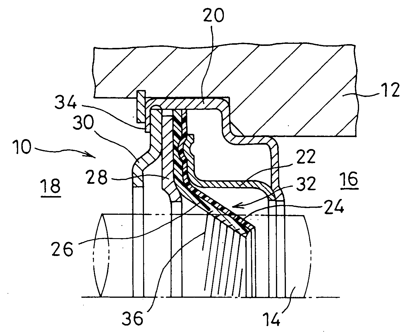
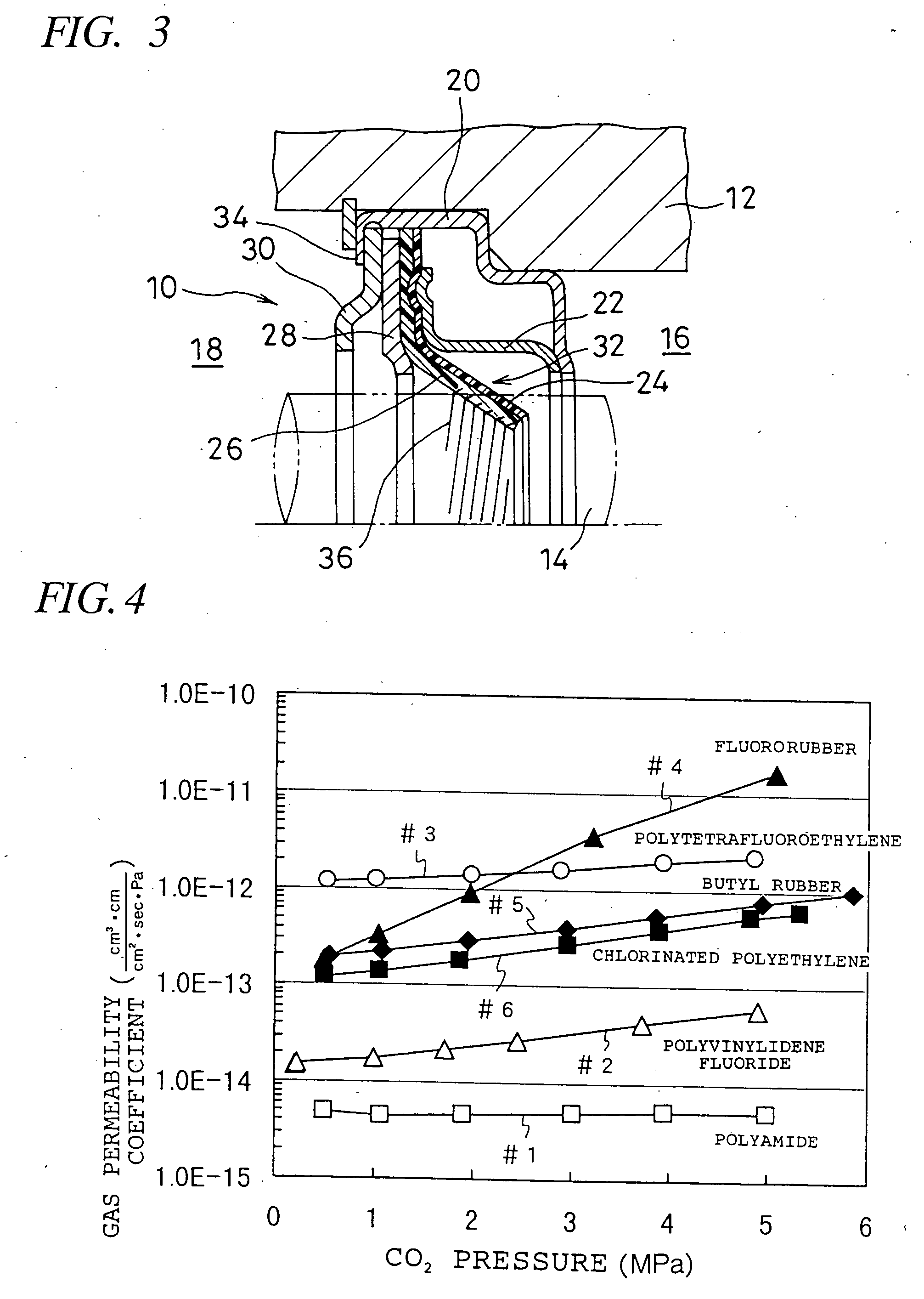
Lip-type high pressure seal
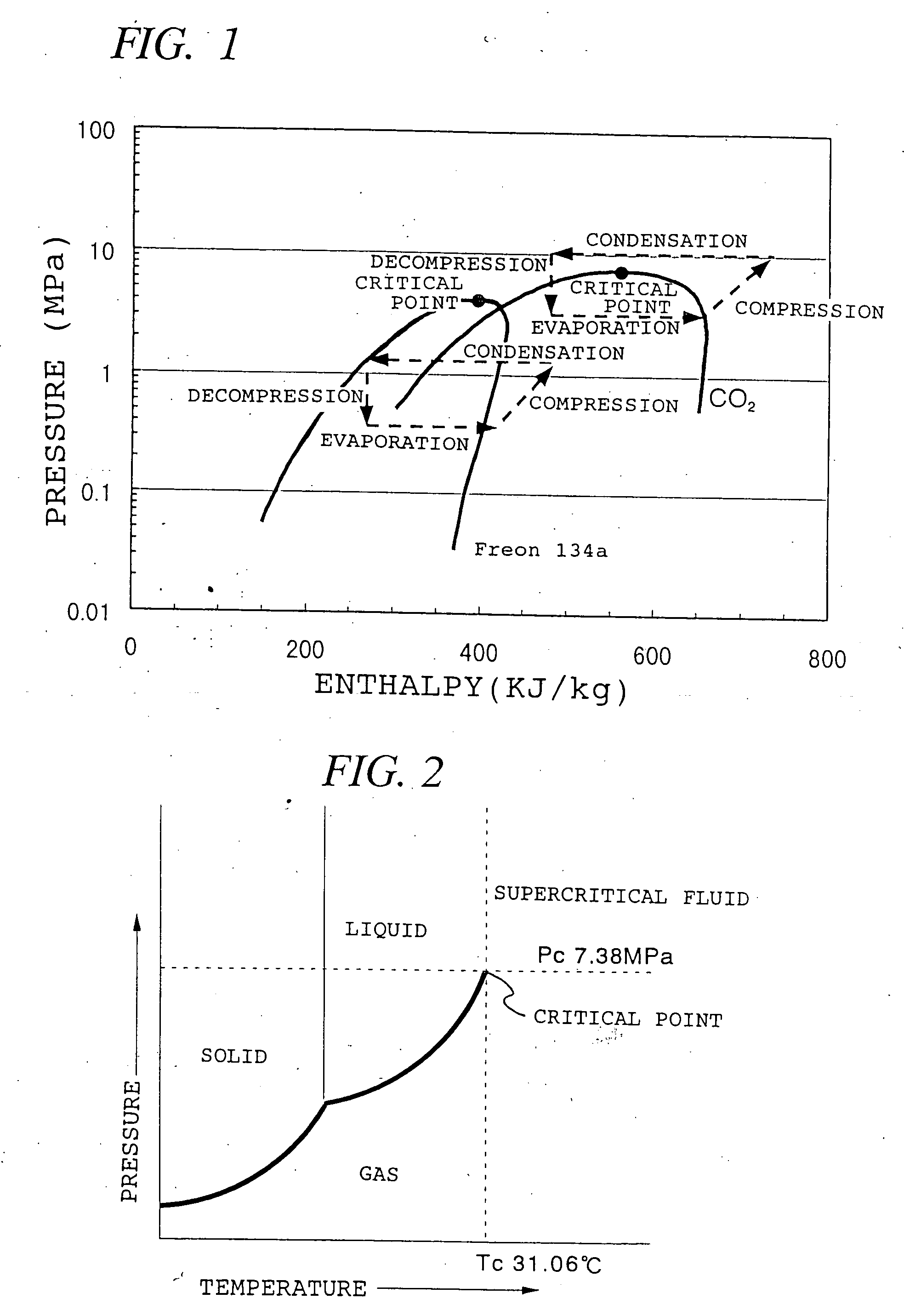
a high-pressure seal and spherical seal technology, which is applied in the direction of engine seals, mechanical equipment, electrochemical variables, etc., can solve the problems of carbon dioxide gas passing a supercritical state, the shaft seal of the compressor is subjected to an extremely high pressure which has never been experienced, and the carbon dioxide gas is caused to pass a supercritical state, etc., to achieve low modulus of elasticity, minimize gas leakage, and high modulus of elasticity
- Summary
- Abstract
- Description
- Claims
- Application Information
AI Technical Summary
Benefits of technology
Problems solved by technology
Method used
Image

Examples
example 1
[0062] A sheet (0.6 mm in thickness) of PTFE (“Teflon 7-J” made by Mitsui-DuPont Fluorochemical), blended with 20% by weight of carbon powder (CMW-350 made by Chuetsu Graphite) to enhance the wear resistivity, and a sheet (0.5 mm in thickness) of nylon (“Diamilon C-Z” made by Mitshibishi Jushi) were subjected to hot rolling to form a laminated sheet having a total thickness of 1 mm which was then punched into donut-shaped blanks which were heat-formed to obtain #1 sealing lips.
[0063] The #1 sealing lips thus prepared, having a lip inner diameter of 10 mm, were mounted to a rotary shaft-type sliding tester and subjected to CO2 leakage measurement under the condition of a circumferential speed of 1 m / sec at CO2 pressure of 50 atm (5.07 MPa), the measured CO2 leakage being 2.3 cm3 per 24 hours.
[0064] Sealing lips were made in a similar manner by using, in place of the nylon sheet, a sheet of polyvinylidene fluoride (“Neofreon VDF” made by Daikin Kogyo), a sheet of poly-chlorotrifluor...
example 2
[0066] Donut-shaped blanks having an outer diameter of 35 mm and an inner diameter of 10 mm and made by punching a sheet (1.5 mm thick) of nylon (“Diamilon C-Z” made by Mitshibishi Jushi) and donut-shaped blanks having an outer diameter of 15 mm and an inner diameter of 10 mm and made by punching a sheet (0.1 mm thick) of PTFE (“Teflon 7-J” made by Mitsui-DuPont Fluorochemical), blended with 20% by weight of carbon powder (CMW-350 made by Chuetsu Graphite), were superposed in a concentric fashion and were heat pressed to form #1 sealing lips. The ratio of the thickness of the PTFE sheet with respect to the thickness of the nylon sheet was 6.25%.
[0067] The #1 sealing lips thus prepared were mounted to the sliding tester and subjected to carbon dioxide gas leakage measurement under the condition of carbon dioxide gas pressure of 1 atm (0.101 MPa) and 60 atm (6.08 MPa), respectively, while the tester shaft was rotated (circumferential speed of 1 m / sec) and held stationary, respectivel...
PUM
| Property | Measurement | Unit |
|---|---|---|
| pressure | aaaaa | aaaaa |
| pressure | aaaaa | aaaaa |
| pressure | aaaaa | aaaaa |
Abstract
Description
Claims
Application Information