
Planar waveguide based grating device and spectrometer for species-specific wavelength detection

a grating device and wavelength detection technology, applied in the field of spectroscopy, can solve the problems of high equipment cost, large equipment size and high equipment cost, and the inability to use general wavelength detection equipment for the detection of different species, and achieve the effect of a higher index of refraction

Inactive Publication Date: 2005-07-14
VALORBEC PARTNERSHIP
View PDF17 Cites 69 Cited by
  • Summary
  • Abstract
  • Description
  • Claims
  • Application Information

AI Technical Summary

Benefits of technology

[0013] The apparatus may also include an electronic subsystem for collecting signals from the array for processing and correlation, and allowing the processed signal to be interpreted for information about a system being studied using the radiation incident to the input edge of the device.

Problems solved by technology

However, widespread application of known detection techniques has been hampered by the typically large size and high cost of equipment.
Hence, using a general wavelength detection equipment for the detection of different species becomes highly demanding due to the wider range of wavelength and finer wavelength resolution required in such applications.
In a spectrometer, all signature wavelengths are generally imaged on a detector array with constant array spacing, such that a large number of detector array elements is required in order to cover a full wavelength range of interest, leading to increased equipment costs.
This results in unused detector elements corresponding to non-excited wavelengths.
Known wavelength detection equipment is also characterized by relatively large required sample quantities, as well as long light paths between the sample and a detection unit, which affects equipment size.

Method used


Image

  • Planar waveguide based grating device and spectrometer for species-specific wavelength detection
  • Planar waveguide based grating device and spectrometer for species-specific wavelength detection
  • Planar waveguide based grating device and spectrometer for species-specific wavelength detection

Examples


Embodiment Construction

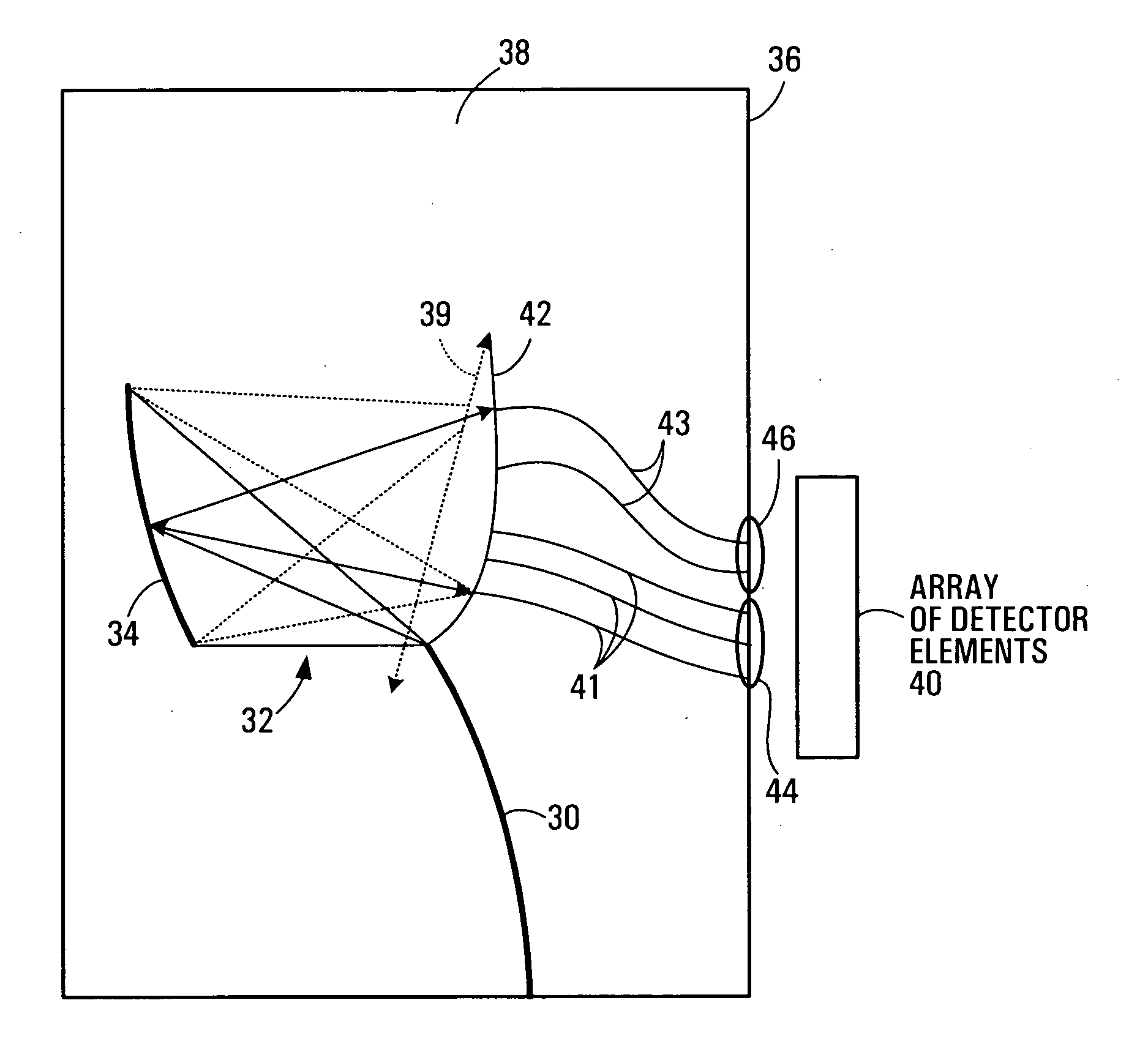
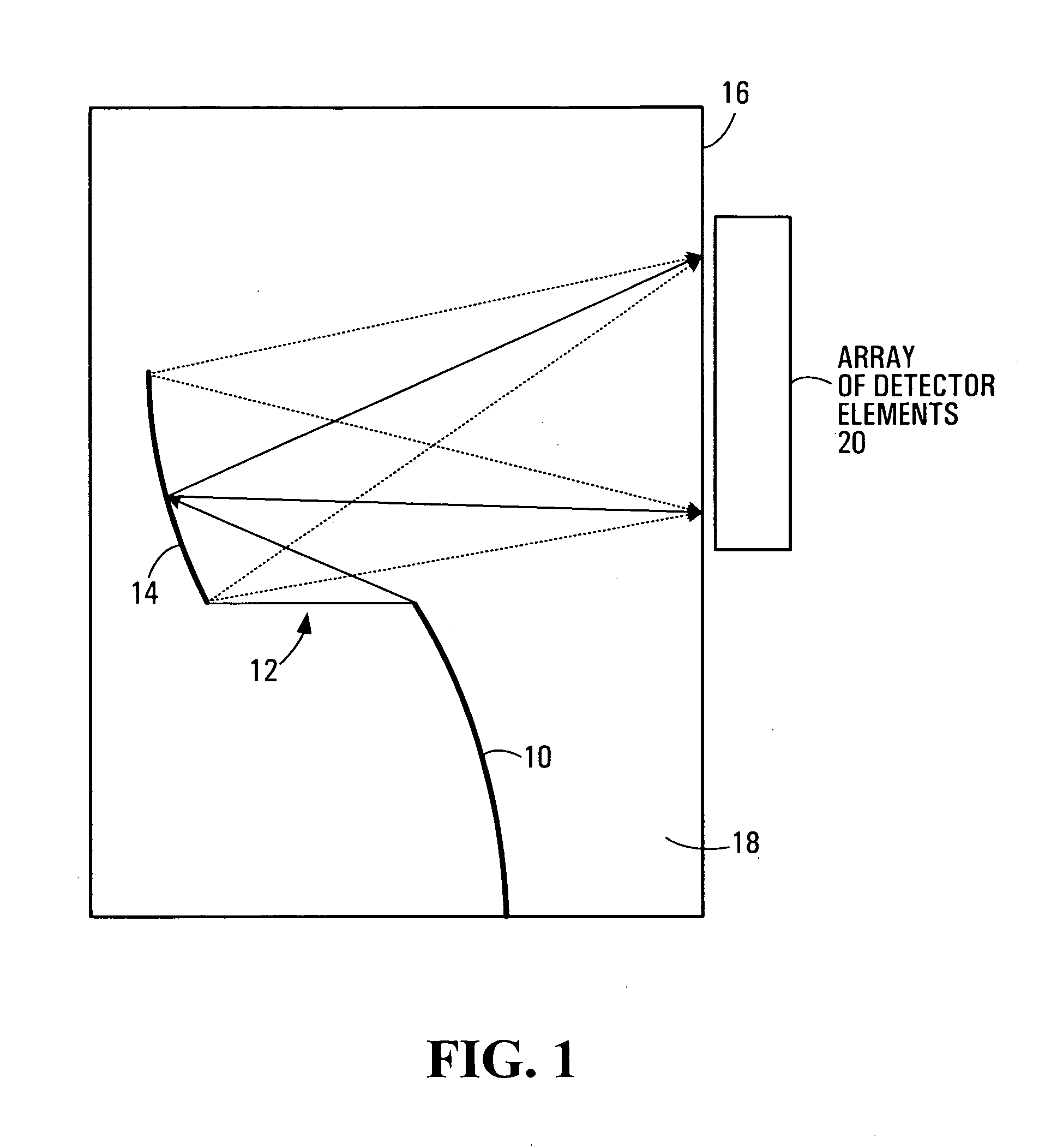
[0033]FIG. 1 is a diagram of a known waveguide based spectrometer. As shown, the spectrometer comprises an input waveguide 10, a slab or planar waveguide section 12, and a diffractive construct 14, fabricated on a thin planar optical substrate 18. An array 20 of detecting elements is adjacent, and typically attached, to an edge 16 of the substrate 18.

[0034] The waveguide based spectrometer shown in FIG. 1 is adapted for equally spaced wavelengths. Light is guided along the input waveguide 10, where it enters the slab waveguide section 12, allowing the light to spread out and cover the diffractive construct 14. The diffractive construct 14 may, for example, be an Echelle grating or the phase-delayed waveguide array of an AWG (Arrayed Waveguide Grating) device. The diffractive construct 14 separates different wavelengths into different positions along an image line at the edge 16.

[0035] The image line produced by the diffractive construct in FIG. 1 is a substantially straight line, ...


PUM


Abstract

Planar waveguide based grating devices and spectrometers, for species-specific wavelength detection for example, are disclosed. A planar waveguide spectrometer apparatus may have a microfluidic channel or compartment microfabricated integrally with a planar waveguide or hybrid assembled with the planar waveguide and optically coupled thereto. The planar waveguide may also include a thin planar substrate which is made of a transparent waveguiding optical material and has a planar multilayer, one or more input waveguides, a waveguide-based spectrometer, and one or more output waveguides integrally formed thereon. An apparatus which incorporates a planar waveguide, a diffractive construct for diffracting light through the planar waveguide onto a curved image surface, and a plurality of output waveguides emanating from the curved image surface at locations selected to extract predetermined wavelengths or wavelength ranges, is also disclosed.

Description

CROSS-REFERENCE TO RELATED APPLICATION [0001] This application claims the benefit of U.S. Provisional Patent Application Ser. No. 60 / 534,696, filed on Jan. 8, 2004, entitled “PLANAR WAVEGUIDE BASED GRATING DEVICE AND SPECTROMETER FOR SPECIES-SPECIFIC WAVELENGTH DETECTION”, and incorporated in its entirety herein by reference.FIELD OF THE INVENTION [0002] This invention relates generally to spectroscopy and, in particular, to planar waveguide based grating devices therefor. BACKGROUND [0003] The miniaturization and integration of spectrographic equipment, using MEMS (Micro Electromechanical Systems) devices, for example, draw great attention for the potential application of spectrographic techniques to different fields of technology. Wavelength signature detection, for example, has immense potential for application in such fields as telecommunications, biological sensing, chemical sensing, and sensing of other material properties that respond through spectral variation of light. Chem...

Claims


Application Information

Patent Timeline
IPC IPC(8): G01J3/28G01N21/05G01N21/31G01N21/64G02B6/34
CPCB82Y10/00B82Y20/00G01J3/0259G01J3/2803G01N21/05G01N21/31G01N2021/0346G01N21/645G01N2021/058G01N2021/6482G01N2021/6484G02B6/12007G01N21/6428
Inventor PACKIRISAMY, MUTHUKUMARANBALAKRISHNAN, ASHOK
Owner VALORBEC PARTNERSHIP
Learn More