Fuel cell system with a control unit

Active Publication Date: 2005-07-14
ROBERT BOSCH GMBH
View PDF4 Cites 5 Cited by
  • Summary
  • Abstract
  • Description
  • Claims
  • Application Information

AI Technical Summary

Benefits of technology

[0018] At least one supply line for supplying the intermediately-stored energy to the load is advantageously located between the electrical load and the intermediate stor

Problems solved by technology

If moistening is inadequate due to unfavorable operating conditions, resistances in th

Method used


Image

  • Fuel cell system with a control unit
  • Fuel cell system with a control unit
  • Fuel cell system with a control unit

Examples


Embodiment Construction

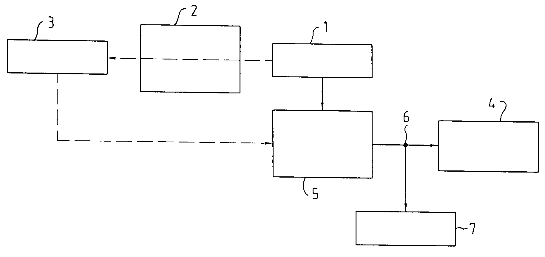
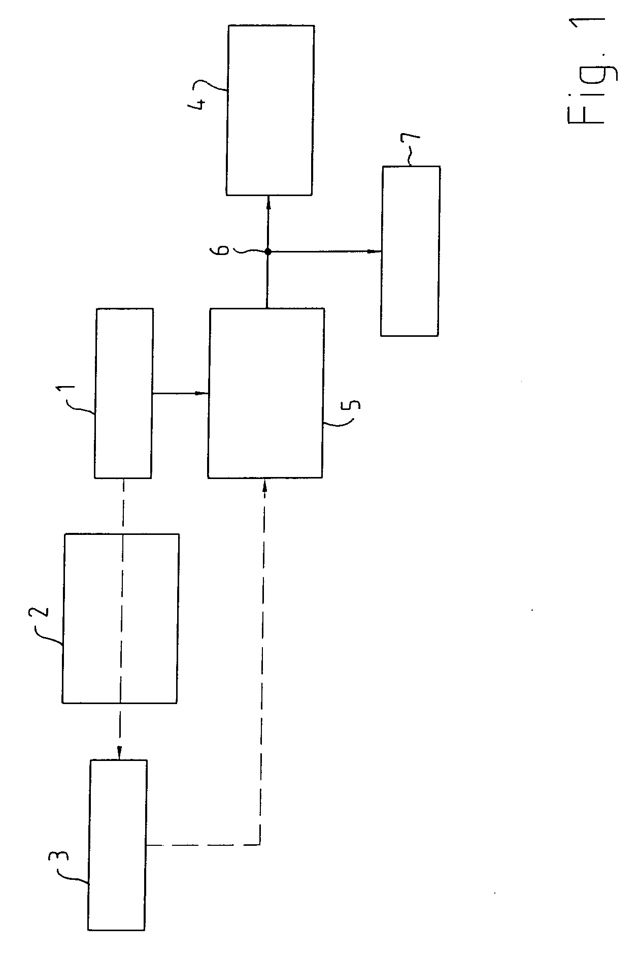
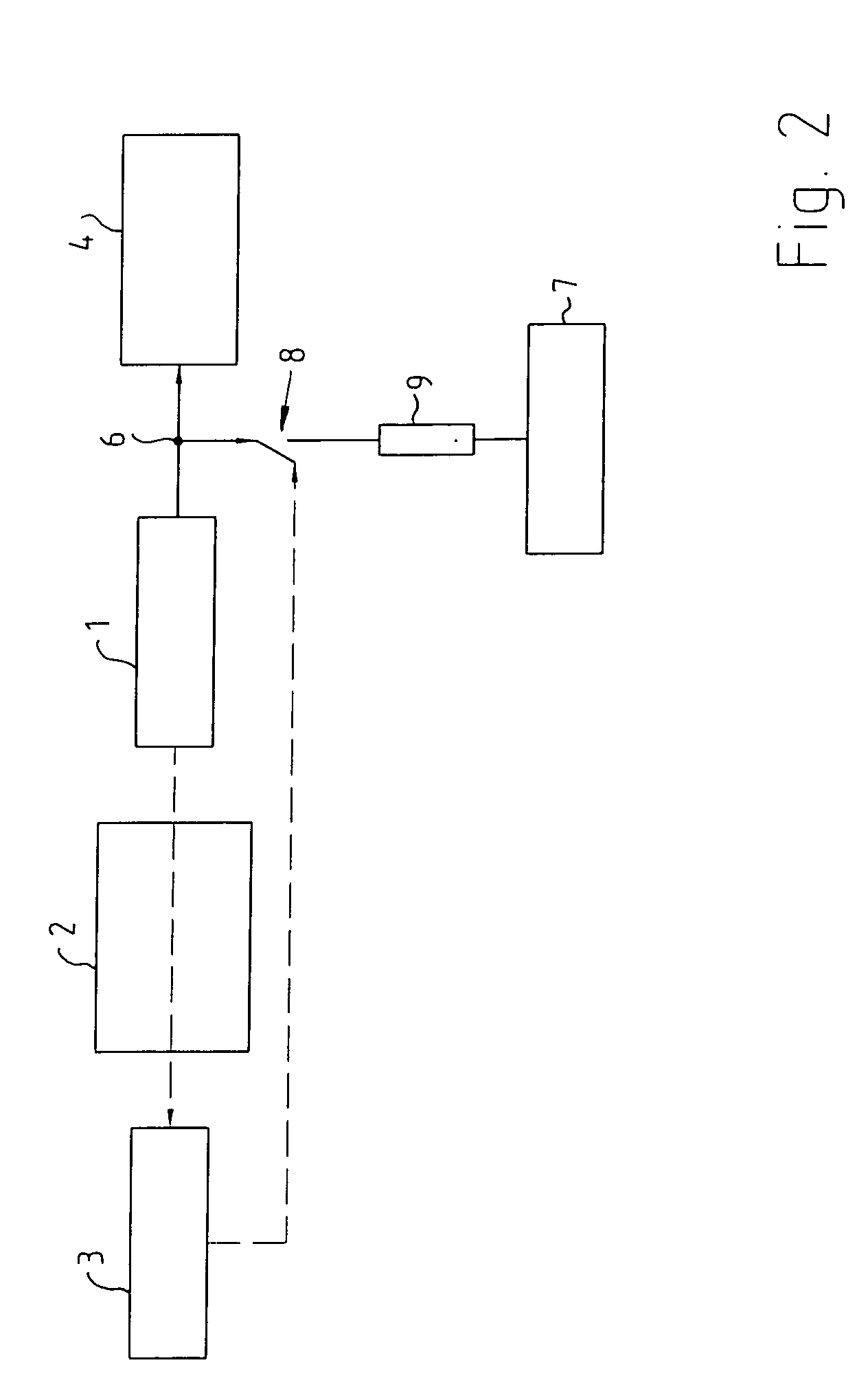
[0022]FIGS. 1 and 2 are both schematic sections of a fuel cell system shown in block diagrams. A fuel cell 1 is monitored by a monitoring unit 2. Monitoring unit 2, in particular an impedance spectroscopy system, a diagnostic unit, which functions according to the state-of-function principle, for example, or the like, transmits to control unit 3 the state of fuel cell 1 and / or advantageous parameters of fuel cell 1, such as the degree of hydration of a membrane of fuel cell unit 1. The state of the absence of water in fuel cell 1 can be sensed at selected load states, among other things, by comparing stored characteristic curves or determining the high-frequency resistance, for example. Highly diverse methods and strategies for this are already known according to the related art.

[0023] In the first variant of the present invention according to FIG. 1, fuel cell 1 transfers its power to an electrical load 4 via a DC / DC converter 5. Via a branch 6, which is located between fuel cell ...


PUM


Abstract

Disclosed is a fuel cell system with a control unit (3) for controlling and/or regulating at least one fuel cell unit (1), whereby the fuel cell unit (1) includes at least one membrane monitored by the control unit (3), and an electrical load (4) is provided, in particular an electric drive motor and/or at least one load on the vehicle electrical system, whereby the moistening of the fuel cell membrane is improved. This is achieved according to the present invention by the fact that the control unit (3) includes at least one additional electrical load (5, 7) for an additional power output from the fuel cell unit (1) which is dependent at least on the moistening of the membrane.

Description

BACKGROUND OF THE INVENTION [0001] The present invention relates to a fuel cell system with a control unit for controlling and / or regulating at least one fuel cell unit. [0002] Fuel cells are considered to be significant as future drive options and / or electrical power sources for motor vehicles. The type of fuel cell discussed most often is the “polymer electrolyte membrane fuel cell” (PEM fuel cell), which functions at temperatures below 1000 Celsius. Other types of fuel cells are also common. [0003] For example, current flow in PEM fuel cells is related to adequate moistening of the membrane. If moistening is inadequate due to unfavorable operating conditions, resistances in the cell invariably increase and, if this condition persists, the cell can be destroyed. Maintaining adequate moisture in all operating states is essential to the effective and safe operation of fuel cells. SUMMARY OF THE INVENTION [0004] The object of the present invention is to propose a fuel cell system wit...

Claims


Application Information

Patent Timeline
IPC IPC(8): H01M8/04H01M8/10H01M16/00
CPCH01M8/04119H01M8/04529H01M8/04649H01M8/0485H01M8/0494Y02E60/56H01M2250/20H01M2250/40Y02T90/32Y02E60/50H01M2250/00Y02T90/40
Inventor SALIGER, RAINERBACKES, MARKUS
Owner ROBERT BOSCH GMBH
Why Eureka
Try Eureka