Anode and battery

Inactive Publication Date: 2005-07-14
SONY CORP
View PDF3 Cites 67 Cited by
  • Summary
  • Abstract
  • Description
  • Claims
  • Application Information

AI Technical Summary

Benefits of technology

[0033] According to the sixth anode and the sixth battery of the invention, the thin film layer containing nickel and titanium is provided on the anode active material layer. Therefore, reaction between the anode active material layer and an electrolyte, and structural destruction of the anode active material layer due to expansion and shrinkage of the anode active material layer can be inhibited. In addition, separation of t

Problems solved by technology

However, in the case of using cobalt acid lithium for a cathode and graphite for an anode, which is currently a typical mode for the lithium secondary batteries, the battery capacity is in a saturated state, and it is extremely difficult to greatly obtain a high capacity of the battery.
However, when charge and discharge are repeated, these anodes are pulverized and miniaturized due to significant expansion and shrinkage of an active material, current collecting characteristics are lowered, and dissolution reaction of an electrolytic solution is promoted due to an increased surface area, so that their cycle characteristics are extremely poor.
However, even when such an anode is used, sufficient cycle characteristics cannot be obtained, since there is a problem such as separation between the current collector and the active material and generation of crinkling in the current collector due to expansion and shrinkage of the active material associated with charge and discharge.
There is also a problem that the reaction with the electrolyte associated with charge and discharge induces deterioration of the capacity.
However, in the case where

Method used


Image

  • Anode and battery
  • Anode and battery
  • Anode and battery

Examples


first embodiment

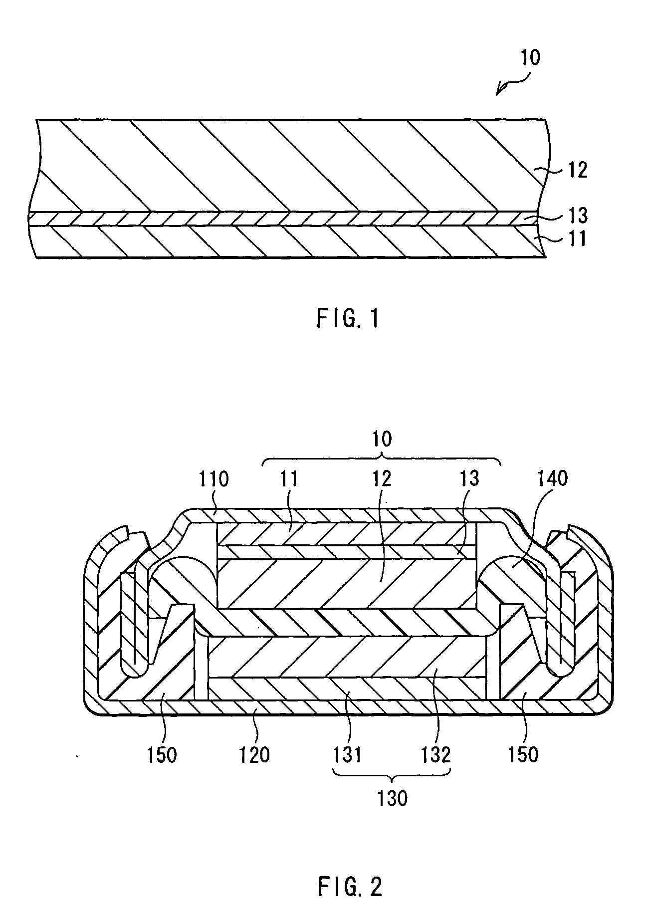
[0049]FIG. 1 shows a simplified construction of an anode 10 according to a first embodiment of the invention. The anode 10 of this embodiment has, for example, an anode current collector 11, an anode active material layer 12 provided for the anode current collector 11, and an interlayer 13 provided between the anode current collector 11 and the anode active material layer 12. The anode active material layer 12 and the interlayer 13 can be formed on both sides or a single side of the anode current collector 11.

[0050] The anode current collector 11 is preferably made of a metal material having high conductivity. In particular, the anode current collector 11 is preferably made of a metal material containing at least one of metal elements which do not form an intermetallic compound with lithium. When the intermetallic compound is formed with lithium, expansion and shrinkage arise associated with charge and discharge, structural destruction arises, and current collecting characteristics...

second embodiment

[0094]FIG. 5 shows a simplified construction of an anode 20 according to a second embodiment of the invention. The anode 20 has, for example, an anode current collector 21 and an anode active material layer 22 provided on the anode current collector 21. The anode active material layer 22 can be formed on both sides or a single side of the anode current collector 21.

[0095] The anode current collector 21 contains a material having superelasticity or shape-memory effect, such as an alloy at least as a part of the anode current collector 21. When such material is contained, even if the anode active material layer 22 is expanded or shrunk associated with charge and discharge, its stress can be relaxed and separation of the anode active material layer 22 can be inhibited. Definitions of the superelasticity and the shape-memory effect are as described in the first embodiment.

[0096] Further, as a material having superelasticity or shape-memory effect, a material which does not form an int...

third embodiment

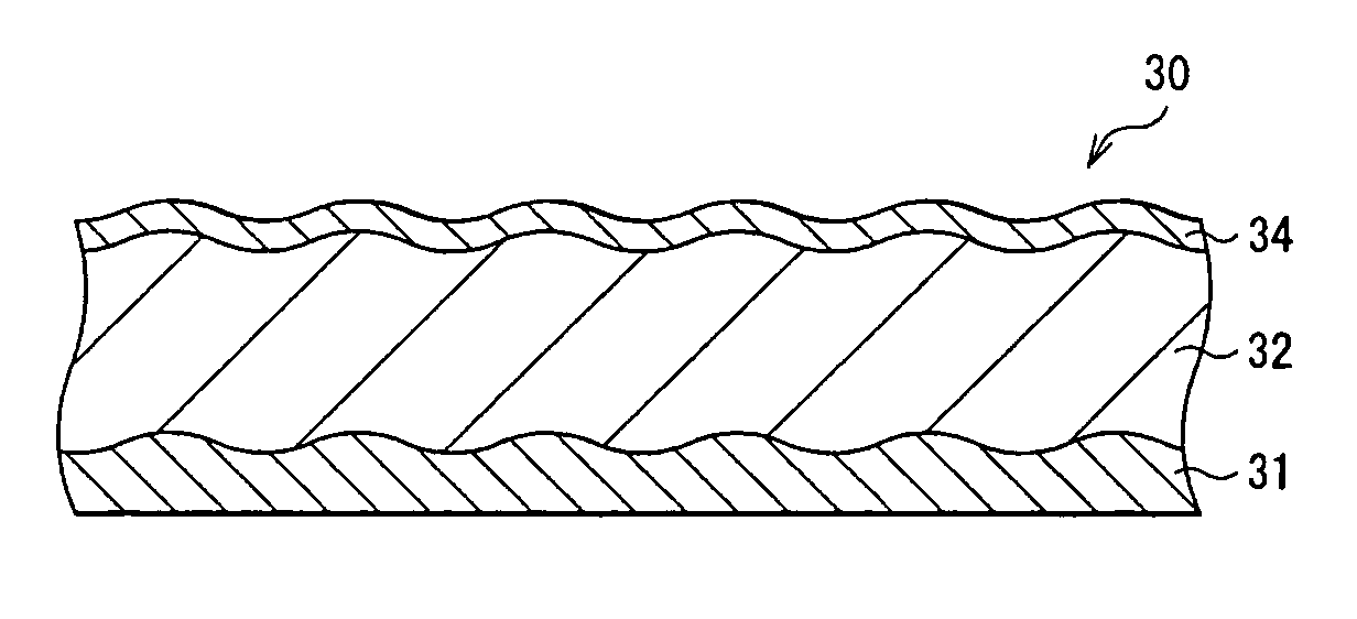
[0110]FIG. 8 shows a simplified construction of an anode 30 according to a third embodiment of the invention. The anode 30 has, for example, an anode current collector 31, an anode active material layer 32 provided on the anode current collector 31, and a thin film layer 34 provided on the anode active material layer 32. The anode current collector 31, the anode active material layer 32, and the thin film layer 33 are layered in this order. The anode active material layer 32 and the thin film layer 33 can be formed on both sides or a single side of the anode current collector 31.

[0111] The anode current collector 31 is preferably made of a metal material containing at least one of metal elements which do not form an intermetallic compound with lithium. When the intermetallic compound is formed with lithium, expansion and shrinkage arise associated with charge and discharge, structural destruction arises, and current collecting characteristics become lowered. In addition, an ability...


PUM

PropertyMeasurementUnit
Surface roughnessaaaaaaaaaa
Ratioaaaaaaaaaa
Memory effectaaaaaaaaaa

Abstract

The invention provides an anode capable of relaxing stress due to expansion and shrinkage of an anode active material layer associated with charge and discharge, or an anode capable of reducing structural destruction of the anode active material layer and reactivity between the anode active material layer and an electrolyte associated with charge and discharge, and a battery using it. The anode active material layer contains an element capable of forming an alloy with Li, for example, at least one from the group consisting of simple substances, alloys, and compounds of Si or Ge. An interlayer containing a material having superelasticity or shape-memory effect is provided between an anode current collector and the anode active material layer. Otherwise, the anode current collector is made of the material having superelasticity or shape-memory effect. Otherwise, a thin film layer containing the material having superelasticity or shape-memory effect is formed on the anode active material layer.

Description

BACKGROUND OF THE INVENTION [0001] 1. Field of the Invention [0002] The present invention relates to an anode in which an anode current collector is provided with an anode active material layer, and a battery using it. [0003] 2. Description of the Related Art [0004] In recent years, in connection with high-performance and multi-function of mobile devices, high capacities of secondary batteries, the power source for the mobile devices have been desired earnestly. As a secondary battery which meets this demand, there is a lithium secondary battery. However, in the case of using cobalt acid lithium for a cathode and graphite for an anode, which is currently a typical mode for the lithium secondary batteries, the battery capacity is in a saturated state, and it is extremely difficult to greatly obtain a high capacity of the battery. Therefore, from old times, using metallic lithium (Li) for an anode has been considered. However, in order to put this anode to practical use, it is necessa...

Claims


Application Information

Patent Timeline
IPC IPC(8): B32B15/00B32B15/01H01M4/02H01M4/134H01M4/40H01M4/66H01M10/052H01M10/36
CPCH01M4/134H01M4/38H01M4/66H01M4/661H01M4/667Y10T428/12944H01M10/0431H01M10/052H01M2004/027Y02E60/122Y10T428/12806H01M4/70H01M4/386Y02E60/10H01M4/02H01M10/05
Inventor KONISHIIKE, ISAMUTAKADA, TOMOOKAWASE, KENICHIMIYAKI, YUKIO
Owner SONY CORP
Why Eureka
Try Eureka