Motor controller
- Summary
- Abstract
- Description
- Claims
- Application Information
AI Technical Summary
Benefits of technology
Problems solved by technology
Method used
Image

Examples
first embodiment
[0025] A controller for a DC brushless motor according to the present invention will now be described.
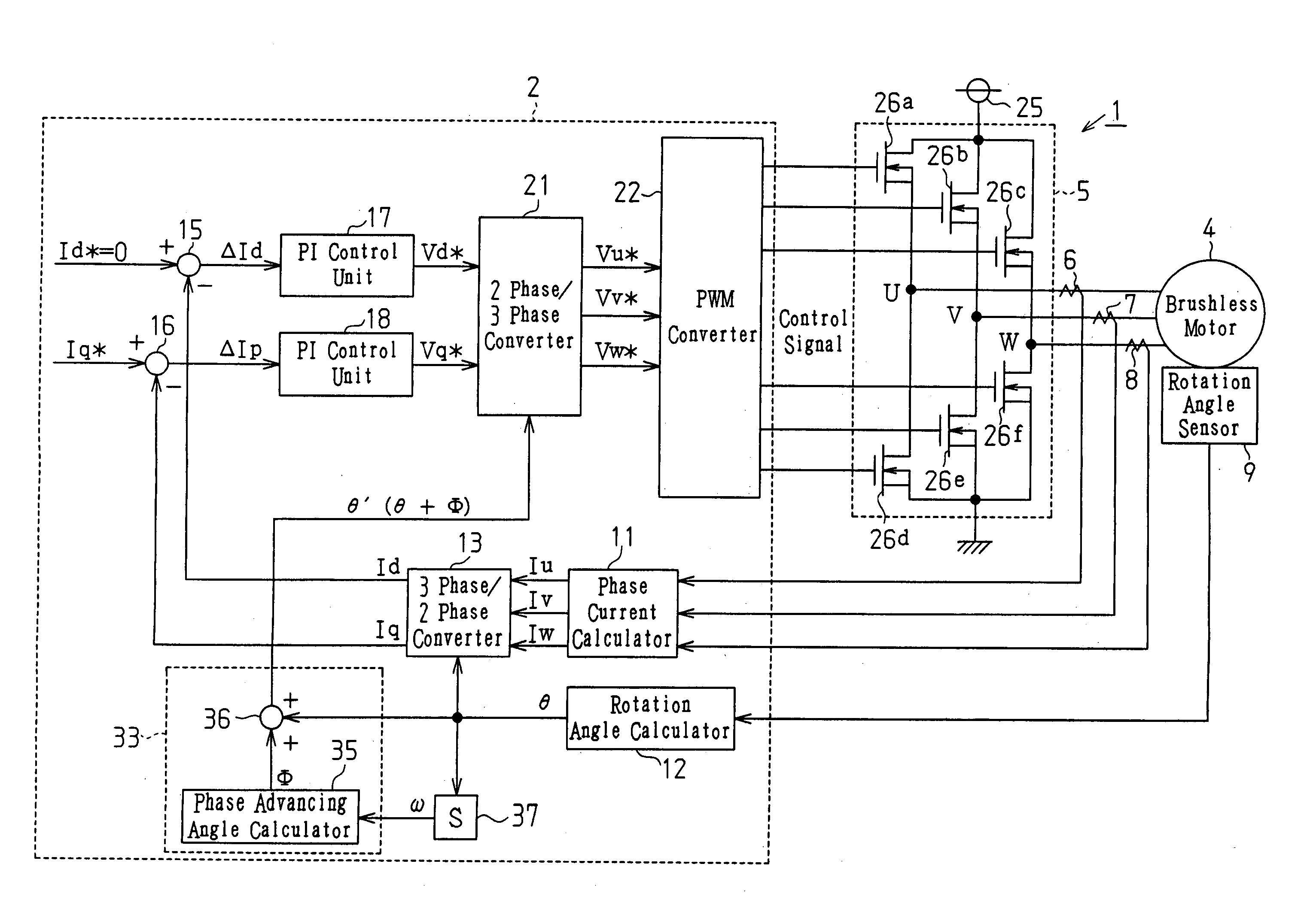
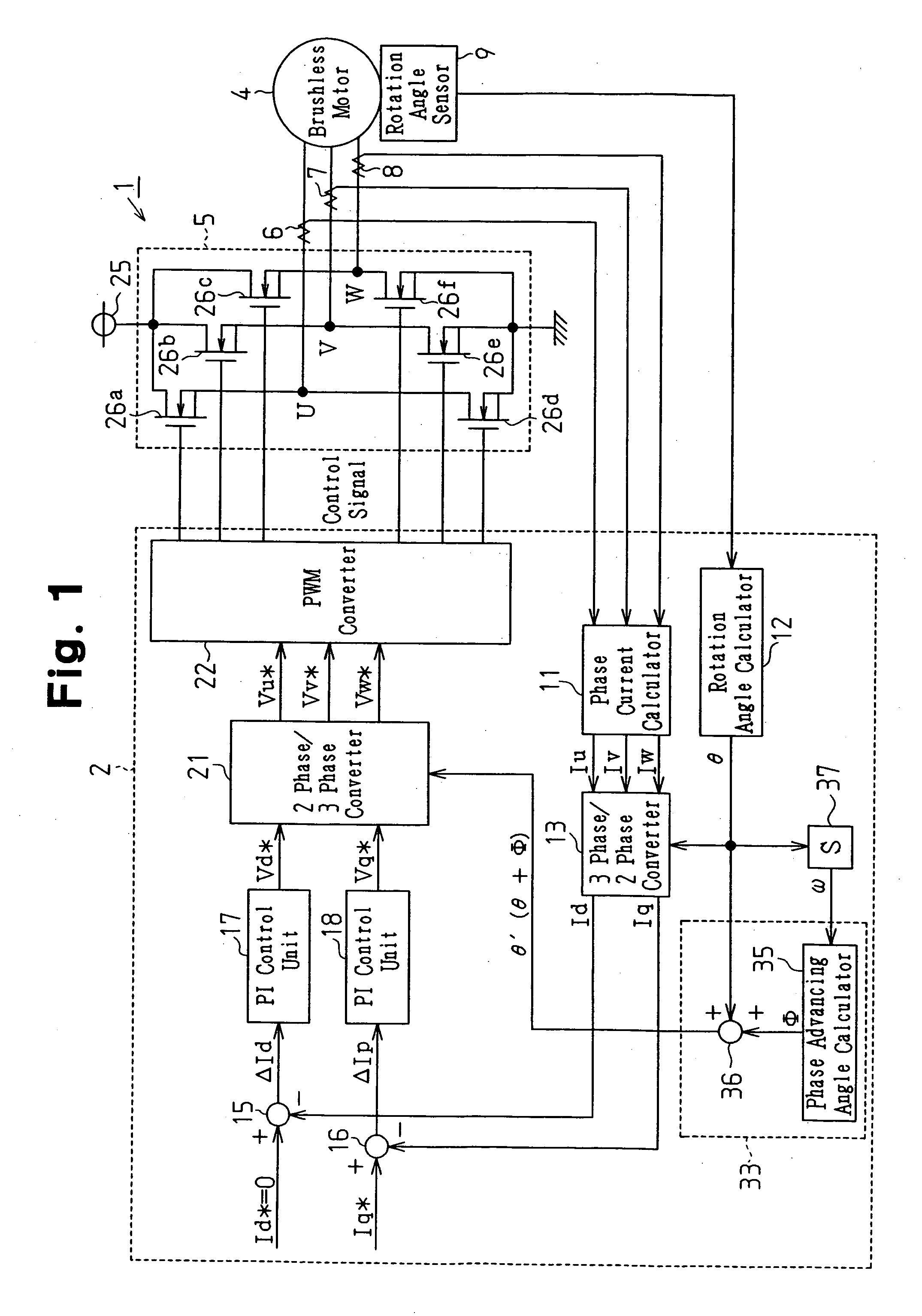
[0026] As shown in FIG. 1, the controller 1 includes a control circuit 2, for generating a motor control signal, and an output circuit 5, for supplying drive power of three phases (U, V, and W) to a brushless motor 4 in accordance with the motor control signal.
[0027] The control circuit 2 is connected to current sensors 6, 7, and 8, which are respectively used for detecting phase current values Iu, Iv, and Iw provided to the brushless motor 4, and a rotation angle sensor 9, which detects the rotation angle θ (electric angle) of the brushless motor 4. The control circuit 2 generates the motor control signal as described below based on the detected phase current values Iu, Iv, and Iw and the rotation angle θ.
[0028] The detection signals of the current sensors 6 to 8 are provided to a phase current calculator 11. The detection signal of the rotation angle sensor 9 is provided to a ro...
second embodiment
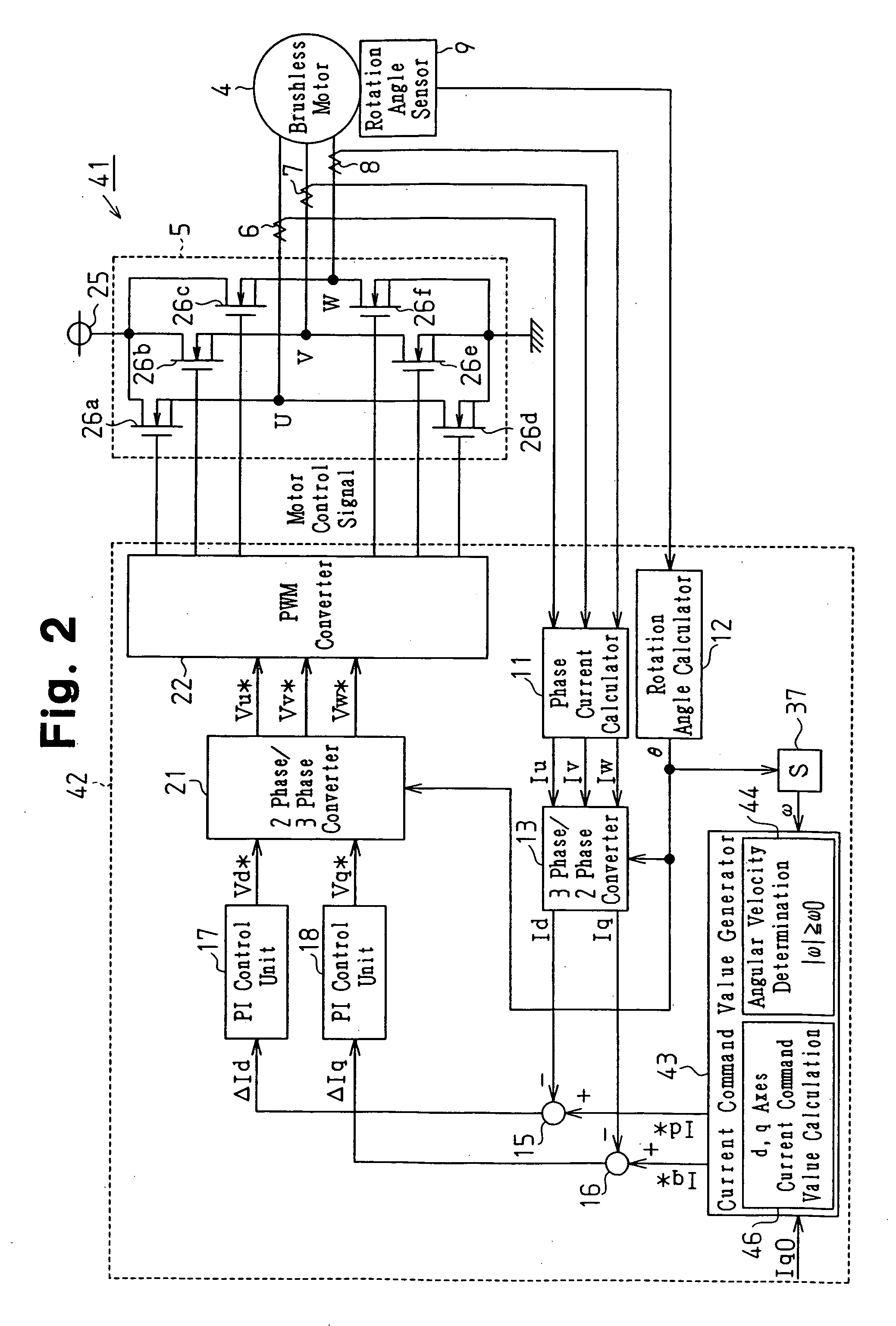
[0052]FIG. 3 is a flowchart of the control performed by the current command value generator 43. When the q-axis current command value Iq0 and the angular velocity ω are input to the current command value generator 43 (S201, 202), the angular velocity determination circuit 44 first determines whether the absolute value of the input angular velocity ω is greater than or equal to a predetermined threshold value, that is, an angular velocity ω0 (S203). In the second embodiment, the angular velocity ω0 is the angular velocity in which the delay angle φ becomes 19° in the above equation of φ=tan−1(ω·L / R).
[0053] Then, if |ω|≧ω0 is satisfied in step S203 (YES in S203), the d, q axes current command value calculator 46 calculates the d-axis current command value Id* and the q-axis current command value Iq* in accordance with the equations of Id*=−|Ig0|×sinΦ0 and Iq*=Iq0×cosΦ0 (S204). The phase advancing angle Φ0 is the delay angle φ (in the second embodiment 19°) corresponding to the angular...
third embodiment
[0071] As shown in FIG. 7, when the q-axis current command value Iq0 and the angular velocity ω are input to the current command value generator 53 (S301, 302), the angular velocity determination circuit 54 first determines whether |ω|·L / R is less than or equal to a predetermined value α (in the third embodiment α=1) that is set in advance (S303) The phase advancing angle calculator 55 then calculates the phase advancing angle Φ′ in accordance with the determination of the angular velocity determination circuit 54 (S304, S305).
[0072] More specifically, when the angular velocity determination circuit 54 determines that |ω|·L / R≦α is satisfied in step S303 (YES in S303), the phase advancing angle calculator 55 calculates the delay angle φ of the phase of the phase current with respect to the phase of the phase voltage command based on the function of the angular velocity ω and the motor inductance L and calculates the phase advancing angle Φ′ corresponding to the delay angle φ (S304). ...
PUM
 Abstract
Description
Claims
Application Information
 - R&D Engineer
- R&D Manager
- IP Professional
- Industry Leading Data Capabilities
- Powerful AI technology
- Patent DNA Extraction
Browse by: Latest US Patents, China's latest patents, Technical Efficacy Thesaurus, Application Domain, Technology Topic.
© 2024 PatSnap. All rights reserved.Legal|Privacy policy|Modern Slavery Act Transparency Statement|Sitemap